The deprecated sysfs ABI
Platforms which use the “gpiolib” implementors framework may choose to
configure a sysfs user interface to GPIOs. This is different from the
debugfs interface, since it provides control over GPIO direction and
value instead of just showing a gpio state summary. Plus, it could be
present on production systems without debugging support.
Given appropriate hardware documentation for the system, userspace could
know for example that GPIO #23 controls the write protect line used to
protect boot loader segments in flash memory. System upgrade procedures
may need to temporarily remove that protection, first importing a GPIO,
then changing its output state, then updating the code before re-enabling
the write protection. In normal use, GPIO #23 would never be touched,
and the kernel would have no need to know about it.
Again depending on appropriate hardware documentation, on some systems
userspace GPIO can be used to determine system configuration data that
standard kernels won’t know about. And for some tasks, simple userspace
GPIO drivers could be all that the system really needs.
Сравнение sysfs и uapi
С помощью нового драйвера рассмотрим отличия между двумя системами с точки зрения пользователя.
uapi
uapi
uapi
uapi
Polling on events
В документации ядра для sysfs указано использовать EPOLLPRI и EPOLLERR (или exceptfds для select), это в принципе характерно для любого вызова sysfs_notify необязательно именно для подсистемы gpio.
Для uapi достаточно EPOLLIN.
Читаем мы событие с временной меткой и типом GPIOEVENT_EVENT_RISING_EDGE или GPIOEVENT_EVENT_FALLING_EDGE.
EPOLLET для uapi работает согласно документации на epoll.
labels
Имя контакта gpioN к которому так все привыкли, вообще говоря, каноническим не является, а используется если контакту не было присвоено имя, например в Device Tree.
Попробуем gpio-mockup с опцией gpio_mockup_named_lines:
Как мы видим имя контакта приобрело вид gpio_chip_label-gpio_offset, но это справедливо только для драйвера gpio-mockup.
Способа «угадать» заранее, существует ли имя для контакта, не используя uapi не представляется возможным, а поиск экспортированной «именованной» линии затруднен, если имя заранее не известно (опять же если известно, то нам для однозначной идентификации необходимо имя и смещение на известном gpiochip).
uapi
Интерфейс uapi позволяет нам без инициализации видеть имена линий:
С соответствующим файлом device tree (пример взят из документации ядра):
Мы бы видели имя в struct gpioline_info для каждого контакта, к сожалению, мало кто именует контакты, даже для распостраненных SBC.
Теперь перечислим преимущества недоступные старому интерфейсу.
Основным преимуществом я считаю временную метку, которая присваивается событию в верхней половине обработчика прерывания. Что незаменимо для приложений, которым важным является точность измерения времени между событиями.
Если позволяет драйвер устройства, линия дополнительно может быть сконфигурирована как открытый коллектор (GPIOLINE_FLAG_OPEN_DRAIN) или открытый эммитер (GPIOLINE_FLAG_OPEN_SOURCE), данное нововведение как раз может быть легко перенесено в sysfs, но этого не будет так как Линус Ваерли против.
Так же новый api позволяет присваивать каждому контакту пользовательские ярлыки при инициализации в struct gpiohandle_request поле consumer_label.
И в заключение позволяет «читать» и «писать» сразу группу состояний для контактов.
Заключение по сравнению
Субъективно, uapi выглядит более громоздким, чем sysfs, но не стоит забывать, что сравнивали мы управление через стандартные утилиты GNU cat и echo и C код, если сравнивать C код для каждого из интерфейсов, получится приблизительно тоже самое по сложности и объему.
Важным моментом является, что в случае использование sysfs линия остается инициализированной пока пользователь не попросит обратного или до перезагрузки. uapi освобождает линию сразу после закрытия файлового дескриптора.
WiringPi
WiringPi is a GPIO access library for the Raspberry Pi. Written in C, it is usable from C or C++ or any language than can call C APIs. Third party bindings for a number a number of languages including Ruby, Python, and Perl are also available.
Released under a GNU LGPLv3 license. it is available from Raspbian Linux or you can build it from source.
It supports a similar API to the Wiring IDE supported on Arduino microcontrollers, making it easier to port hardware control code between the Raspberry Pi and Arduino platforms.
As well as the Raspberry Pi GPIO pins, it also supports some add-on boards like the PiFace and Gertboard.
The gpio command we looked at in an earlier blog post is part of WiringPi.
The library provides basic functions to read and write pins, including pullup and pulldown resistors and hardware PWM. It also provides routines for software delays down to the microsecond level. There is also support for higher level protocols including serial, SPI, and I2C.
In practice, WiringPi is very easy to use. Functions are defined in the header file <wiringPi.h>. You call a setup function to initialize the library, set the GPIO pin modes, and then call methods to read or write. The trickiest issue is probably getting the pin numbers correct — WiringPi uses a pin numbering convention based on the Broadcom SOM channel names, not physical pins. The documentation covers this (and the command gpio readall will also show it in tabular form). There is also a function you can call to convert physical pin numbers to WiringPi numbers.
Here is a simple example that toggles an LED connected to pin 18. It should be straightforward to understand from the source code:
/*
Example of programming GPIO from C or C++ using the WiringPi library
on a Raspberry Pi.
Will continuously toggle GPIO24 (physical pin 18) at a 500 millisecond
rate.
Jeff Tranter <<a href=»mailto:jtranter@ics.com»>jtranter@ics.com</a>>
*/#include <wiringPi.h>int main(void){
// Red LED: Physical pin 18, BCM GPIO24, and WiringPi pin 5.
const int led = 5;
wiringPiSetup();
pinMode(led, OUTPUT);
while (1) {
digitalWrite(led, HIGH);
delay(500);
digitalWrite(led, LOW);
delay(500);
}
return ;}
Here is an example of reading an input and showing its level:
/*
Example of programming GPIO from C or C++ using the WiringPi library
on a Raspberry Pi.
Will read a pushbutton switch on GPIO6 (physical pin 31) every 500
milliseconds and report the status. seconds and then exit.
Jeff Tranter <<a href=»mailto:jtranter@ics.com»>jtranter@ics.com</a>>
*/#include <stdio.h>#include <wiringPi.h>int main(void){
// Switch: Physical pin 31, BCM GPIO6, and WiringPi pin 22.
const int button = 22;
wiringPiSetup();
pinMode(button, INPUT);
while (1) {
if (digitalRead(button) == LOW) {
fprintf(stderr, «Switch is pressed\n»);
} else {
fprintf(stderr, «Switch is released\n»);
}
delay(500);
}
return ;}
This final example will cycle through three LEDs in a binary pattern. If the pushbutton is pressed, it will turn off all LEDs and exit.
/*
Example of programming GPIO from C or C++ using the WiringPi library
on a Raspberry Pi.
Will cycle through three LEDs in a binary pattern. If the pushbutton is
pressed, it will turn off all LEDs and exit.
Jeff Tranter <<a href=»mailto:jtranter@ics.com»>jtranter@ics.com</a>>
*/#include <stdio.h>#include <stdlib.h>#include <wiringPi.h>int main(void){
// Red LED: Physical pin 18, BCM GPIO24, and WiringPi pin 5.
const int led1 = 5;
// Green LED: Physical pin 22, BCM GPIO25, and WiringPi pin 6.
const int led2 = 6;
// Yellow LED: Physical pin 29, BCM GPIO5, and WiringPi pin 21.
const int led3 = 21;
// Switch: Physical pin 31, BCM GPIO6, and WiringPi pin 22.
const int button = 22;
wiringPiSetup();
pinMode(led1, OUTPUT);
pinMode(led2, OUTPUT);
pinMode(led3, OUTPUT);
pinMode(button, INPUT);
fprintf(stderr, «Running on Raspberry Pi revision %d\n», piBoardRev());
while (1) {
for (int i = ; i < 8; i++) {
if (i & 1) {
digitalWrite(led1, HIGH);
} else {
digitalWrite(led1, LOW);
}
if (i & 2) {
digitalWrite(led2, HIGH);
} else {
digitalWrite(led2, LOW);
}
if (i & 4) {
digitalWrite(led3, HIGH);
} else {
digitalWrite(led3, LOW);
}
delay(100);
}
if (digitalRead(button) == LOW) {
digitalWrite(led1, LOW);
digitalWrite(led2, LOW);
digitalWrite(led3, LOW);
exit(1);
}
}}
I did a few performance measurements on the code in demo2.c. Running the loop with no delays produced a GPIO pin cycling at a rate of almost 12 MHz on a Raspberry Pi 3. The main reason for the high performance is that it uses direct register access to avoid the kernel/user space context switching and other overhead needed with sysfs.
Using delays of delayMicroseconds(10) produced a very consistent and accurate 50 kHz square wave.
Using the SPI Bus
I really liked the following description from Neil’s Log Book: The SPI (Serial Peripheral Interface) protocol behaves like a ring buffer so that whenever the master sends a byte to the slave, the slave sends a byte back to the master. The slave can use this behavior to return a status byte, a response to a previous byte, or null data (the master may choose to read the returned byte or ignore it). The bus operates on a 4-wire interface.
provides easy access to the 2 SPI channels available on the Raspberry. The functionality depends on ‘s SPI library. Please note that you may need to issue the command before starting your application (or as a when your application starts) if the SPI kernel drivers have not been loaded.
In order to use an SPI channel you MUST always set the or (depending on the channel you want to use) before calling the method. If the property is not set beforehand the SPI channel will fail initialization. See an example below:
Example of using the SPI Bus
Note: In order to enable the second SPI channel (SPI1) you need to add to the config file.
Features
This library enables developers to use the various Raspberry Pi’s hardware modules:
- Provides access to the official Raspberry Pi Camera module.
- Provides information on this Raspberry Pi’s CPU and form factor.
- Provides access to the Raspberry Pi’s GPIO as a collection of GPIO Pins.
- Provides access to the 2-channel SPI bus.
- Provides access to the functionality of the I2C bus.
- Provides access to The PI’s Timing and threading API.
Peripherals
We offer an additional package with helpful classes to use peripherals, many of them are from pull requests from our contributors. The current set of peripherals supported are:
- Infrared Sensor HX-1838
- Led Strip APA-102C
- NFC/RFID Controller MFRC-522
- DHT family digital relative humidity and temperature sensors:
- DHT11
- DHT12
- DHT21 / AM-2301
- DHT22 / AM-2302
- OLED Display SSD-1306
- Generic Button connected to GPIO
- GY-521 MPU6050 Accelerometer
- Ultrasonic Sensor HC-SR04
- ADS1015 and ADS1115 I2C Analog-to-Digital Converter devices
Platform Data
Finally, GPIOs can be bound to devices and functions using platform data. Board
files that desire to do so need to include the following header:
#include <linux/gpio/machine.h>
GPIOs are mapped by the means of tables of lookups, containing instances of the
gpiod_lookup structure. Two macros are defined to help declaring such mappings:
GPIO_LOOKUP(key, chip_hwnum, con_id, flags)
GPIO_LOOKUP_IDX(key, chip_hwnum, con_id, idx, flags)
where
In the future, these flags might be extended to support more properties.
- Note that:
-
-
GPIO line names are not guaranteed to be globally unique, so the first
match found will be used. -
GPIO_LOOKUP() is just a shortcut to GPIO_LOOKUP_IDX() where idx = 0.
-
A lookup table can then be defined as follows, with an empty entry defining its
end. The ‘dev_id’ field of the table is the identifier of the device that will
make use of these GPIOs. It can be NULL, in which case it will be matched for
calls to with a NULL device.
struct gpiod_lookup_table gpios_table = {
        .dev_id = "foo.0",
        .table = {
                GPIO_LOOKUP_IDX("gpio.0", 15, "led", , GPIO_ACTIVE_HIGH),
                GPIO_LOOKUP_IDX("gpio.0", 16, "led", 1, GPIO_ACTIVE_HIGH),
                GPIO_LOOKUP_IDX("gpio.0", 17, "led", 2, GPIO_ACTIVE_HIGH),
                GPIO_LOOKUP("gpio.0", 1, "power", GPIO_ACTIVE_LOW),
                { },
        },
};
And the table can be added by the board code as follows:
gpiod_add_lookup_table(&gpios_table);
The driver controlling “foo.0” will then be able to obtain its GPIOs as follows:
struct gpio_desc *red, *green, *blue, *power;

red = gpiod_get_index(dev, "led", 0, GPIOD_OUT_HIGH);
green = gpiod_get_index(dev, "led", 1, GPIOD_OUT_HIGH);
blue = gpiod_get_index(dev, "led", 2, GPIOD_OUT_HIGH);

power = gpiod_get(dev, "power", GPIOD_OUT_HIGH);
Since the “led” GPIOs are mapped as active-high, this example will switch their
signals to 1, i.e. enabling the LEDs. And for the “power” GPIO, which is mapped
as active-low, its actual signal will be 0 after this code. Contrary to the
legacy integer GPIO interface, the active-low property is handled during
mapping and is thus transparent to GPIO consumers.
A set of functions such as is available to work with
the new descriptor-oriented interface.
Boards using platform data can also hog GPIO lines by defining GPIO hog tables.
struct gpiod_hog gpio_hog_table[] = {
        GPIO_HOG("gpio.0", 10, "foo", GPIO_ACTIVE_LOW, GPIOD_OUT_HIGH),
        { }
};
And the table can be added to the board code as follows:
gpiod_add_hogs(gpio_hog_table);
Hello GPIO
Vediamo ora un piccolo esempino che ci aiuterà a capire le basi per controllare qualche pin.
Questo qua sotto è il circuito che andremo ad attaccare al nostro Raspberry
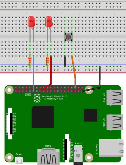
Abbiamo quindi bisogno di due led, due resistenze da 330Ω e un pulsante.
Il cavo blu andrà collegato al pin numero 11 che è il GPIO17, il cavo rosso al numero 15 che è il GPIO22 e il cavo arancione al numero 36 che è il GPIO16.
Il circuito farà una cosa molto semplice: di default sarà acceso il led di sinistra ma, tendendo premuto il pulsante, spegniamo quello di sinistra e accendiamo quello di destra. Quindi dovremo mantenere alto il GPIO17 in uscita e quando leggeremo sul GPIO16 «premuto», abbassiamo GPIO17 e alziamo GPIO22.. easy!
Per programmare useremo python perché tutto è pronto out-of-the-box nel senso che le librerie che ci permettono di mandare e ricevere segnali tramite interfaccia GPIO, sono già installate.
Se avete già familiarità con Arduino, tutto vi saprà di già visto
hello-gpio.py
Python
#importiamo le librerie per il controllo dell’interfaccia GPIO
import RPi.GPIO as GPIO
#definiamo il sistema di riferimento dei pin. Con GPIO.BCM usiamo i numeri GPIO dei pin e non il numero dei pin.
#Ad esempio con GPIO.BCM per riferirci al pin GPIO17, usiamo 17 (e non 11). Per indicare che
#ci si riferisce al numero del pin, si usa GPIO.setmode(GPIO.BOARD)
GPIO.setmode(GPIO.BCM)
#definiamo il numero GPIO dei pin in gioco
pinButton = 16
pinLedLeft = 17
pinLedRight = 22
#definiamo che pinLedLeft e pinLedRight sono due pin di output
GPIO.setup(pinLedLeft , GPIO.OUT)
GPIO.setup(pinLedRight , GPIO.OUT)
#definiamo che pinButton è un pin di input con un valore di default a 1
GPIO.setup(pinButton, GPIO.IN, pull_up_down=GPIO.PUD_UP)
#inizializziamo il led di destra spento
GPIO.output(pinLedRight, GPIO.LOW)
while 1:
#quando il pulsante è premuto…
if GPIO.input(pinButton):
#…accendi il led di destra e spegni quello di sinistra
GPIO.output(pinLedRight, GPIO.HIGH)
GPIO.output(pinLedLeft , GPIO.LOW)
else:
#…altrimenti torna nella configurazione iniziale
GPIO.output(pinLedRight, GPIO.LOW)
GPIO.output(pinLedLeft , GPIO.HIGH)
|
1 |
#importiamo le librerie per il controllo dell’interfaccia GPIO importRPi.GPIO asGPIO GPIO.setmode(GPIO.BCM) pinButton=16 pinLedLeft=17 pinLedRight=22 GPIO.setup(pinLedLeft,GPIO.OUT) GPIO.setup(pinLedRight,GPIO.OUT) GPIO.setup(pinButton,GPIO.IN,pull_up_down=GPIO.PUD_UP) GPIO.output(pinLedRight,GPIO.LOW) while1 #quando il pulsante è premuto… ifGPIO.input(pinButton) #…accendi il led di destra e spegni quello di sinistra GPIO.output(pinLedRight,GPIO.HIGH) GPIO.output(pinLedLeft,GPIO.LOW) else #…altrimenti torna nella configurazione iniziale GPIO.output(pinLedRight,GPIO.LOW) GPIO.output(pinLedLeft,GPIO.HIGH) |
Come vedete anche voi è molto intuitivo. Per esercizio provate a modificare il codice in modo che una volta cliccato il pulsante si lascia acceso il led che prima era spento e spegnere quello che prima era acceso.
Per ora è tutto. Se avete delle domande, non esitate a lasciarci un commento.
A breve nuovi articoli a riguardo, a presto!
Andrea Salvi
Parts of the Raspberry Pi 3 B+ Model
Parts of Raspberry Pi 3 B+
Processor: The BCM2837B0 processor is the main component of this tiny board that helps in carrying out a large set of instructions based on mathematical and logical formulas. BCM2837B0 is a 1.4GHz 64bit ARM quad-core Cortex A53 processor.
RAM: RAM used in R-Pi 3 B+ is 1GB LPDDR2 SDRAM (similar to the previous version)
GPU: It stands for graphics processing unit and is used for performing out the image calculation. The GPU uses OpenGL ES version 2.0, hardware-accelerated OpenVG API, and 1080p30 H.264 high-profile decode. It can provide up to 1Gpixel/s, 1.5Gtexel/s, or 24 GFLOPs of a general-purpose computer.
USB Ports: Similar to model B, model B+ also consists of 4 USB ports. Thus removing the hassle of connecting the USB hub in order to increase the ports.
Micro USB Power Source Connector: This connector is used for delivering 5V power to the board. It consumes approx. 170 to 200mA more power than model B. The power connector is also repositioned in the new B+ model and placed next to the HDMI socket.
HDMI and Composite Connection: Both the audio output socket and the video composite socket reside in a single 4-pole 3.5mm socket which is placed near the HDMI port, and now all the power and audio-video composite socket are placed on the one side of the board which gives it a clean and nice look.
USB Hard Drive: The board is capable of using an external USB hard drive.
PoE: B+ model comes with a facility of Power over Ethernet (PoE); a new feature added in this device which allows us to power the board using the ethernet cables.
Other Changes: The B+ version also comes with other improvements like the SD memory slot is replaced by a micro SD memory card slot (works similar to the previous version). The status LEDs on the board now only contain red and green colors and are relocated to the opposite end of the board.
4.4. Pin factories
An alternative (or additional) method of configuring gpiozero objects to use
remote pins is to create instances of
objects, and use them when
instantiating device objects. For example, with no environment variables set:
from gpiozero import LED
from gpiozero.pins.pigpio import PiGPIOFactory
from time import sleep

factory = PiGPIOFactory(host='192.168.1.3')
led = LED(17, pin_factory=factory)

while True
    led.on()
    sleep(1)
    led.off()
    sleep(1)
This allows devices on multiple Raspberry Pis to be used in the same script:
from gpiozero import LED
from gpiozero.pins.pigpio import PiGPIOFactory
from time import sleep

factory3 = PiGPIOFactory(host='192.168.1.3')
factory4 = PiGPIOFactory(host='192.168.1.4')
led_1 = LED(17, pin_factory=factory3)
led_2 = LED(17, pin_factory=factory4)

while True
    led_1.on()
    led_2.off()
    sleep(1)
    led_1.off()
    led_2.on()
    sleep(1)
You can, of course, continue to create gpiozero device objects as normal, and
create others using remote pins. For example, if run on a Raspberry Pi, the
following script will flash an LED on the controller Pi, and also on another Pi
on the network:
from gpiozero import LED
from gpiozero.pins.pigpio import PiGPIOFactory
from time import sleep

remote_factory = PiGPIOFactory(host='192.168.1.3')
led_1 = LED(17)  # local pin
led_2 = LED(17, pin_factory=remote_factory)  # remote pin

while True
    led_1.on()
    led_2.off()
    sleep(1)
    led_1.off()
    led_2.on()
    sleep(1)
Alternatively, when run with the environment variables
set, the following
script will behave exactly the same as the previous one:
from gpiozero import LED
from gpiozero.pins.rpigpio import RPiGPIOFactory
from time import sleep

local_factory = RPiGPIOFactory()
led_1 = LED(17, pin_factory=local_factory)  # local pin
led_2 = LED(17)  # remote pin

while True
    led_1.on()
    led_2.off()
    sleep(1)
    led_1.off()
    led_2.on()
    sleep(1)
Of course, multiple IP addresses can be used:
from gpiozero import LED
from gpiozero.pins.pigpio import PiGPIOFactory
from time import sleep

factory3 = PiGPIOFactory(host='192.168.1.3')
factory4 = PiGPIOFactory(host='192.168.1.4')

led_1 = LED(17)  # local pin
led_2 = LED(17, pin_factory=factory3)  # remote pin on one pi
led_3 = LED(17, pin_factory=factory4)  # remote pin on another pi

while True
    led_1.on()
    led_2.off()
    led_3.on()
    sleep(1)
    led_1.off()
    led_2.on()
    led_3.off()
    sleep(1)
Note that these examples use the class, which takes a pin
argument to initialise. Some classes, particularly those representing HATs and
other add-on boards, do not require their pin numbers to be specified. However,
it is still possible to use remote pins with these devices, either using
environment variables, or the pin_factory keyword argument:
import gpiozero
from gpiozero import TrafficHat
from gpiozero.pins.pigpio import PiGPIOFactory
from time import sleep

gpiozero.Device.pin_factory = PiGPIOFactory(host='192.168.1.3')
th = TrafficHat()  # traffic hat on 192.168.1.3 using remote pins
This also allows you to swap between two IP addresses and create instances of
multiple HATs connected to different Pis:
import gpiozero
from gpiozero import TrafficHat
from gpiozero.pins.pigpio import PiGPIOFactory
from time import sleep

remote_factory = PiGPIOFactory(host='192.168.1.3')

th_1 = TrafficHat()  # traffic hat using local pins
th_2 = TrafficHat(pin_factory=remote_factory)  # traffic hat on 192.168.1.3 using remote pins
You could even use a HAT which is not supported by GPIO Zero (such as the
Sense HAT) on one Pi, and use remote pins to control another over the
network:
from gpiozero import MotionSensor
from gpiozero.pins.pigpio import PiGPIOFactory
from sense_hat import SenseHat

remote_factory = PiGPIOFactory(host='192.198.1.4')
pir = MotionSensor(4, pin_factory=remote_factory)  # remote motion sensor
sense = SenseHat()  # local sense hat

while True
    pir.wait_for_motion()
    sense.show_message(sense.temperature)
Using the GPIO Pins
Pin reference for the B plus (B+) — Header P1
| BCM | Name | Mode | V | L | R | V | Mode | Name | BCM |
|---|---|---|---|---|---|---|---|---|---|
| 3.3v | 01 | 02 | 5v | ||||||
| 2 | SDA.1 | ALT0 | 1 | 03 | 04 | 5V | |||
| 3 | SCL.1 | ALT0 | 1 | 05 | 06 | GND | |||
| 4 | GPIO. 7 | IN | 1 | 07 | 08 | 1 | ALT0 | TxD | 14 |
| GND | 09 | 10 | 1 | ALT0 | RxD | 15 | |||
| 17 | GPIO. 0 | IN | 11 | 12 | IN | GPIO. 1 | 18 | ||
| 27 | GPIO. 2 | IN | 13 | 14 | GND | ||||
| 22 | GPIO. 3 | IN | 15 | 16 | IN | GPIO. 4 | 23 | ||
| 3.3v | 17 | 18 | IN | GPIO. 5 | 24 | ||||
| 10 | MOSI | IN | 19 | 20 | GND | ||||
| 9 | MISO | IN | 21 | 22 | IN | GPIO. 6 | 25 | ||
| 11 | SCLK | IN | 23 | 24 | 1 | IN | CE0 | 8 | |
| GND | 25 | 26 | 1 | IN | CE1 | 7 | |||
| SDA.0 | IN | 1 | 27 | 28 | 1 | IN | SCL.0 | 1 | |
| 5 | GPIO.21 | IN | 1 | 29 | 30 | GND | |||
| 6 | GPIO.22 | IN | 1 | 31 | 32 | IN | GPIO.26 | 12 | |
| 13 | GPIO.23 | IN | 33 | 34 | GND | ||||
| 19 | GPIO.24 | IN | 35 | 36 | IN | GPIO.27 | 16 | ||
| 26 | GPIO.25 | IN | 37 | 38 | IN | GPIO.28 | 20 | ||
| GND | 39 | 40 | IN | GPIO.29 | 21 |
The above diagram shows the pins of GPIO Header P1. There is an additional GPIO header on the Pi called P5. More info available here
In order to access the pins, use . The pins can have multiple behaviors and fortunately can be iterated, addressed by index, addressed by BCM pin number and provides the pins as publicly accessible properties.
Here is an example of addressing the pins in all the various ways:
Pin Information
All pins have handy properties and methods that you can use to drive them. For example, you can examine the property to find out which features are available on the pin. You can also use the property to get or set the operating mode of the pin. Please note that the value of the property is by default set to Input and it will return the last mode you set the property to.
Digital Read and Write
It is very easy to read and write values to the pins. In general, it is a 2-step process.
- Set the pin mode
- Read or write the bit value
Reading the value of a pin example:
Writing to a pin example
Hardware PWM
Simple code for led dimming:
PwmRange is the maximun value of the pulse width, than means 100% of pulse width. Changing this value allows you to have a more fine or coarse control of the pulse width (default 1024).
PwmRegister is the current pulse width. Changing this value allows you to change the current pulse width and thus the duty cycle.
Duty Cycle is equals to PwmRegister divide by PwmRange. Assuming a PwmRange value of 1024 (default), we have:
| PwmRegister | Duty Cycle |
|---|---|
| 0% | |
| 256 | 25% |
| 512 | 50% |
| 768 | 75% |
| 1024 | 100% |
Note: Hardware PWM can be used only in GPIO12, GPIO13, GPIO18 and GPIO19.
Software PWM
Simple code for led dimming:
SoftPwmRange is the range of the pulse width, than means 100% of pulse width (We notice better performance using a range value of 100).
SoftPwmValue is the current pulse width. Changing this value allows you to change the current pulse width and thus the duty cycle.
Note: Software PWM can be used in any GPIO.
Summary
That wraps up today’s guide on how to use the Raspberry Pi’s GPIO PINs with Python! I hope you’ve gotten a better understanding of the different uses of GPIO and how to use it to interface with sensors and modules for building your own electronics projects.
For more Raspberry Pi resources, please visit the following links:
- How To: 3 Methods to Configure Raspberry Pi WiFi
- 28 Raspberry Pi Linux Commands: A Quick Guide to Use the Command Line for Raspberry Pi
- Build a Raspberry Pi Security Camera using Raspberry Pi Camera!
- Build a Raspberry Pi Line Following Robot!
- Top 35 Raspberry Pi 4 Projects That You Must Try Now
Please follow and like us:
Похожие записи:
 Как устроен генератор постоянного тока
 Наконечники толстостенные, разновидности
 потолочные люстры для натяжных потолков: фото, виды, дизайнерские идеи
 Выбираем и монтируем видеонаблюдение для дачи
 Электроника для начинающих (чарльз платт) [2012, техническая литература, pdf, ebook (изначально компьютерное)]
 Разница между звуковыми волнами и радиоволнами