Summary
As you can see, it is quite easy to use http.server to create a simple web server and integrate your plain Raspberry Pi code with the http.server implementation. Our customised BaseHTTPRequestHandler implementation MyServer class can be easily modified to integrate whatever GET or POST requests that you need to get information from Raspberry Pi, or control GPIO via a web site based on your Raspberry Pi project. No Flask web framework is required and no installation of LAMP is required, at least, not for simple IoT project like this one.
The complete codes two python examples available at my github.
https://youtube.com/watch?v=SRf6HW_b3EE
Gpiozero
A newer GPIO library for the Raspberry Pi is gpiozero . Created by Ben Nuttall of the Raspberry Pi Foundation and other contributors it is released under an MIT-type free software license.
While newer than Rpi.GPIO, it is now generally recommended to use it for new programming. It can have a longer learning because it offers more features that Rpi.GPIO, but the resulting code is usually very clean and readable.
We’ll look at a few simple examples of how to use it.
Documentation is excellent, and presents many «recipes» showing how to control various devices from LEDs to switches to motion sensors, servers, and robots.
Gpiozero should be installed by default on Raspian Linux unless you installed the «lite» version. If needed, it can be installed using the command:
sudo apt install python3-gpiozero
Gpiozero provides may different modules or «interfaces». You typically import the ones you use by name so you can refer to them with a short name. For example:
to allow using the gpiozero.LED module and refer to it as «LED». You can import multiple modules with one import statement, e.g.
from gpiozero import LED, Button
The GPiozero library uses Broadcom (BCM) pin numbering rather than physical pin numbers. That should not normally be a problem. It does define names based on other naming conventions like physical pins that can be used and will be converted to the BCM names. The following examples will all work for an LED that is on GPIO 17 on physical pin 11:
led = LED(17)
led = LED(«GPIO17»)
led = LED(«BCM17»)
led = LED(«BOARD11»)
led = LED(«WPI0»)
led = LED(«J8:11»)
A handy command line tool called «pinout» is part of the library and will graphically show you the GPIO pins for the board it is running on (or any board revision that you specify):
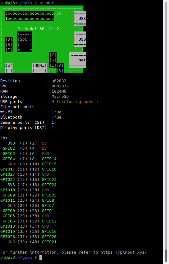
The library is oriented around device and sensor types rather than inputs and outputs. For driving an output connected to an LED, for example, you use the LED module. You create an instance by passing the GPIO name. You can then call various methods like on() and off(). Here is a simple example that flashes and LED:
#!/usr/bin/python3
from gpiozero import LED
from time import sleep
led = LED(24)
while True:
led.on()
sleep(1)
led.off()
sleep(1)
The above loop could also be done by simply calling:
red.blink()
Which blinks an LED, defaulting to a rate of one second on and one second off.
Inputs pins are often connected to buttons, and in this case you can use the Gpiozero Button module, as in this example:
#!/usr/bin/python3
from gpiozero import Button
from time import sleep
button = Button(6)
while True:
if button.is_pressed:
print(«Button is pressed»)
else:
print(«Button is not pressed»)
sleep(1)
We can easily connect a switch so that when a pressed or released event occurs, we drive an LED high or low. This is event drived, so once set up, this works without any polling or further processing:
#!/usr/bin/python3
from gpiozero import LED, Button
from signal import pause
led = LED(24)
button = Button(6)
button.when_pressed = led.on
button.when_released = led.off
pause()
The call to pause() ensures that our Python program does not exit immediately, but rather keeps running until the user interrupts it with Control-C or similar.
Gpiozero has support for many devices — you can explore the documentation and try writing programs of your own. You can also extend it for new types of devices and sensors.
Скорость работы и джиттер
Опрос состояния кнопок и управление светодиодами – события относительно медленные, измеряющиеся десятками и сотнями миллисекунд. Иногда встречаются намного более высокоскоростные сигналы. Например, пульт от телевизора излучает инфракрасные световые импульсы со скоростью 40 тыс. раз в секунду. Несмотря на то, что основной процессор RPi работает на частоте 1 ГГц, работа подсистемы ввода/вывода с такой скоростью не поддерживается по ряду причин, как аппаратных, так и программных. Мы рассмотрим некоторые программные аспекты, касающиеся темы статьи.
RPi работает под управлением многозадачной операционной системы (ОС) Linux. Система может превентивно забирать контроль над вашей программой для выполнения других задач. Все это происходит довольно быстро, так что кажется, будто мышка по-прежнему работает во время выполнения вашей программы, но на самом деле вашей программе и коду драйвера мыши ОС предоставляет лишь короткие промежутки времени.
Обычно это не имеет значения, но когда вам нужна обработка коротких или высокоточных событий, это может стать проблемой, проявляющейся (например) в виде джиттера.
Кроме того, немаловажное значение имеет выбор языка программирования, поскольку некоторые библиотеки подходят лучше, чем другие. Интерпретированные и компилированные коды могут выполняться с разными скоростями
Короче говоря, если требуется очень точная временнáя привязка событий, возможно, придется написать драйвер Linux или использовать внешнее оборудование (например, другой микроконтроллер или логические схемы и генератор).
Одним из хороших вопросов, важных для более полного использования возможностей RPi, является то, насколько быстро можно изменять логические состояния выходов GPIO с помощью библиотек Python, Си и описанного выше командного скрипта.
Чтобы узнать это, был написан код для периодического переключения логического состояния выходного порта, к которому был подключен осциллограф. Результат представлен в Таблице 1.
| Таблица 1. | Максимальная частота переключения выходов при использовании различных языков программирования |
|||||||||||||||
|
Однако всегда важно помнить о джиттере, которым обязательно сопровождается работа ОС Linux. Для случая простого переключения светодиода это, кончено же, не проблема
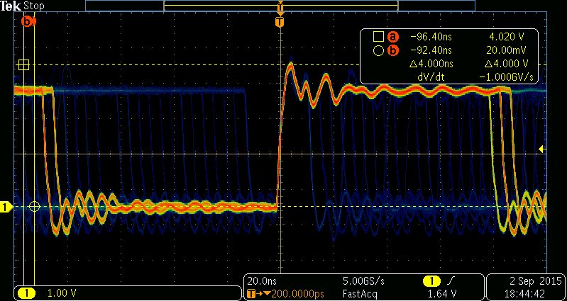
Характер джиттера можно увидеть на осциллографе в режиме наложения нескольких каналов при синхронизации общим сигналом (Рисунок 17)
Обратите внимание, что джиттер может принимать множество значений, несмотря на то, что сигналы дискретно разнесены на 4 нс (250 МГц), что связано с аппаратными особенностями RPi
 |
|
| Рисунок 17. | Следствием использования ОС Linux становится джиттер выходного сигнала. |
Usage
Below is example usage on a Raspberry PI Model B+ V1.2.
To detect/list GPIO character devices:
# gpiodetect
gpiochip0  (54 lines)
To list the I/O lines available on this device:
# gpioinfo pinctrl-bcm2835
gpiochip0 - 54 lines:
        line   0:       "SDA0"       unused   input  active-high
        line   1:       "SCL0"       unused   input  active-high
        line   2:       "SDA1"       unused   input  active-high
        line   3:       "SCL1"       unused   input  active-high
        line   4:  "GPIO_GCLK"       unused   input  active-high
        line   5:  "CAM_GPIO1"       unused   input  active-high
        line   6:    "LAN_RUN"       unused   input  active-high
        line   7:  "SPI_CE1_N"       unused   input  active-high
        line   8:  "SPI_CE0_N"       unused   input  active-high
        line   9:   "SPI_MISO"       unused   input  active-high
        line  10:   "SPI_MOSI"       unused   input  active-high
        line  11:   "SPI_SCLK"       unused   input  active-high
        line  12:         "NC"       unused   input  active-high
        line  13:         "NC"       unused   input  active-high
        line  14:       "TXD0"       unused   input  active-high
        line  15:       "RXD0"       unused   input  active-high
        line  16: "STATUS_LED_N" "ACT" output active-low
        line  17:     "GPIO17"       unused   input  active-high
        line  18:     "GPIO18"       unused   input  active-high
        line  19:         "NC"       unused   input  active-high
        line  20:         "NC"       unused   input  active-high
        line  21:     "GPIO21"       unused   input  active-high
        line  22:     "GPIO22"       unused   input  active-high
        line  23:     "GPIO23"       unused   input  active-high
        line  24:     "GPIO24"       unused   input  active-high
        line  25:     "GPIO25"       unused  output  active-high
        line  26:         "NC"       unused   input  active-high
        line  27:  "CAM_GPIO0"       unused   input  active-high
        line  28:    "CONFIG0"       unused   input  active-high
        line  29:    "CONFIG1"       unused   input  active-high
        line  30:    "CONFIG2"       unused   input  active-high
        line  31:    "CONFIG3"       unused   input  active-high
        line  32:         "NC"       unused   input  active-high
        line  33:         "NC"       unused   input  active-high
        line  34:         "NC"       unused   input  active-high
        line  35:         "NC"       unused   input  active-high
        line  36:         "NC"       unused   input  active-high
        line  37:         "NC"       unused   input  active-high
        line  38:         "NC"       unused   input  active-high
        line  39:         "NC"       unused   input  active-high
        line  40:   "PWM0_OUT"       unused   input  active-high
        line  41:         "NC"       unused   input  active-high
        line  42:         "NC"       unused   input  active-high
        line  43:         "NC"       unused   input  active-high
        line  44:         "NC"       unused   input  active-high
        line  45:   "PWM1_OUT"       unused   input  active-high
        line  46: "HDMI_HPD_P"       unused   input  active-high
        line  47: "SD_CARD_DET"      unused   input  active-high
        line  48:   "SD_CLK_R"       unused   input  active-high
        line  49:   "SD_CMD_R"       unused   input  active-high
        line  50: "SD_DATA0_R"       unused   input  active-high
        line  51: "SD_DATA1_R"       unused   input  active-high
        line  52: "SD_DATA2_R"       unused   input  active-high
        line  53: "SD_DATA3_R"       unused   input  active-high
Display help for the gpioset command:
# gpioset --help
Usage: gpioset   = = ...
Set GPIO line values of a GPIO chip
Options:
  -h, --help:           display this message and exit
  -v, --version:        display the version and exit
  -l, --active-low:     set the line active state to low
  -m, --mode= (defaults to 'exit'):
                tell the program what to do after setting values
  -s, --sec=SEC:        specify the number of seconds to wait (only valid for --mode=time)
  -u, --usec=USEC:      specify the number of microseconds to wait (only valid for --mode=time)
  -b, --background:     after setting values: detach from the controlling terminal

Modes:
  exit:         set values and exit immediately
  wait:         set values and wait for user to press ENTER
  time:         set values and sleep for a specified amount of time
  signal:       set values and wait for SIGINT or SIGTERM
To toggle GPIO25 high for 1 second:
# gpioset --mode=time --sec=1 pinctrl-bcm2835 25=1
Подключение к 5-вольтовй логике
Прямое подключение устройств с 5-вольтовыми логическими выходами к входам RPi может вывести плату из строя. В этом случае есть множество решений.
Если состояние 5-вольтового логического выхода меняется относительно медленно, можно рассмотреть возможность использования резистивного делителя на входе RPi, но к быстрым схемам такой способ не применим. Тогда намного более хорошим решением будет использование буферной микросхемы. Для средних скоростей (до 100 кГц) вполне подойдет схема на N-канальном MOSFET ZVN2110A (Рисунок 16). Эта схема также инвертирует входной сигнал.
 |
|
| Рисунок 16. | Схема простого преобразователя логических уровней. |
Показанный на схеме транзистор можно заменить на ZVNL120A или VN10LP.
При пайке полевых транзисторов следует соблюдать основные меры предосторожности. При сборке устройства сначала установите резистор R3 и только после этого извлеките MOSFET из защитной упаковки и запаяйте в схему
Резистор R3 обеспечит некоторую защиту.
Practice circuit 2
Fix a two-legged button switch on the breadboard. Now, connect one leg of the switch to any GPIO pin, say Pin 7, and connect the other to any 3.3V pin.
#!/usr/bin/python3
import RPi.GPIO as GPIO
import time

cnl = 7
GPIO.setmode(GPIO.BOARD)

# PIN 7 AND 3.3V
# normally 0 when connected 1
GPIO.setup(cnl, GPIO.IN, GPIO.PUD_DOWN)
try:
while(True):
print(GPIO.input(cnl))
time.sleep(1)
except KeyboardInterrupt:
GPIO.cleanup()
print(“Exiting”)
When this program is run, it will print 0 continuously, and when the switch is pressed down (when the circuit is closed) the output will be 1.
Now change the circuit a little. Remove the connection from the 3v3 pin and connect it to any ground pin. Change the program by replacing GPIO.PUD_DOWN with GPIO.PUD_UP. Now run the program, and 1 will be printed continuously. When the switch is pressed down, the output will be 0.
Interrupts
There is a problem with simple input pins, which is that the programmer has to constantly check the input data. To overcome this, we have interrupts known as ‘event-detect’ and a pin can be made to listen to events by calling:
GPIO.add_event_detect(channel, event, callback = my_callback, bouncetime = timeinmilliseconds)
Channel should be an input pin. The various events available are GPIO.RISING for the rising edge (when the signal changes to HIGH from LOW), GPIO.FALLING for the falling edge (when the signal changes from HIGH to LOW), and GPIO.BOTH for both rising and falling edges. The my_callback method contains the interrupt handling code, and will be executed as a separate thread. bouncetime is the minimum amount of time required between two events. If two events occur in succession, within the bouncetime limit, then the second event will be ignored.
Extra Credit: Blinking Light
Here is a slightly more advanced script that blinks the led on and off. The only real difference is that we are gathering user input and using the sleep function to set the amount of time the light is on or off.
Type the following code into the window:
import RPi.GPIO as GPIO ## Import GPIO library
import time ## Import ‘time’ library. Allows us to use ‘sleep’
GPIO.setmode(GPIO.BOARD) ## Use board pin numbering
GPIO.setup(7, GPIO.OUT) ## Setup GPIO Pin 7 to OUT##Define a function named Blink()
def Blink(numTimes,speed):for i in range(0,numTimes):## Run loop numTimesprint «Iteration » + str(i+1)## Print current loopGPIO.output(7,True)## Switch on pin 7time.sleep(speed)## WaitGPIO.output(7,False)## Switch off pin 7time.sleep(speed)## Waitprint «Done» ## When loop is complete, print «Done»GPIO.cleanup()## Ask user for total number of blinks and length of each blink
iterations = raw_input(«Enter total number of times to blink: «)
speed = raw_input(«Enter length of each blink(seconds): «)## Start Blink() function. Convert user input from strings to numeric data types and pass to Blink() as parameters
Blink(int(iterations),float(speed))
…or you may download the completed script here.
Keep in mind that indentation is very important when writing Python code. Use the TAB key to match the formatting of the above code as you write it.
Télécharger la vidéo, regarder gratuitement

8:35
Will Smith Bungee Jumps Out of a Helicopter!
Vues 8 975 805 88%
2:21
New Pokémon Discovered: Introducing Meltan!
Vues 2 179 322 93%
14:34
Vues 400 619 99%
2:49
BTS and Jimmy Fallon Do the Fortnite Dance Challenge
Vues 1 734 240 99%
8:59
Hasan Minhaj’s Groupon Proposal Fail
Vues 397 794 98%
7:33
Archery Trick Shots 2 | Dude Perfect
Vues 6 446 928 99%
11:22
Billie Eilish Reacts To Teens React To Billie Eilish
Vues 1 839 098 99%
13:15
Steelers vs. Buccaneers Week 3 Highlights | NFL 2018
Vues 1 606 619 94%
7:05
Why colleges tolerate fraternities
Vues 953 084 78%
10:16
$10 QUEER EYE TRANSFORMATION (w/ Jon Cozart)
Vues 610 968 93%
20:25
Game Theory: How PewDiePie LOST YouTube to T Series
Vues 2 184 977 91%
14:27
Vues 4 032 012 96%
7:22
DIY 7 INGREDIENT SANDWICH STADIUM
Raspberry Pi GPIO Projects
Now that you’ve seen how easy it is to get started with Raspberry Pi GPIO using Grove, we couldn’t possibly leave you hanging without some project recommendations, could we? With a plethora of projects available thanks to the endless possibilities that GPIO pins offer, I’ll just be providing a few of my favourites today! For a comprehensive list of Raspberry Pi Projects, click here!
1. Raspberry Pi Smart Clock
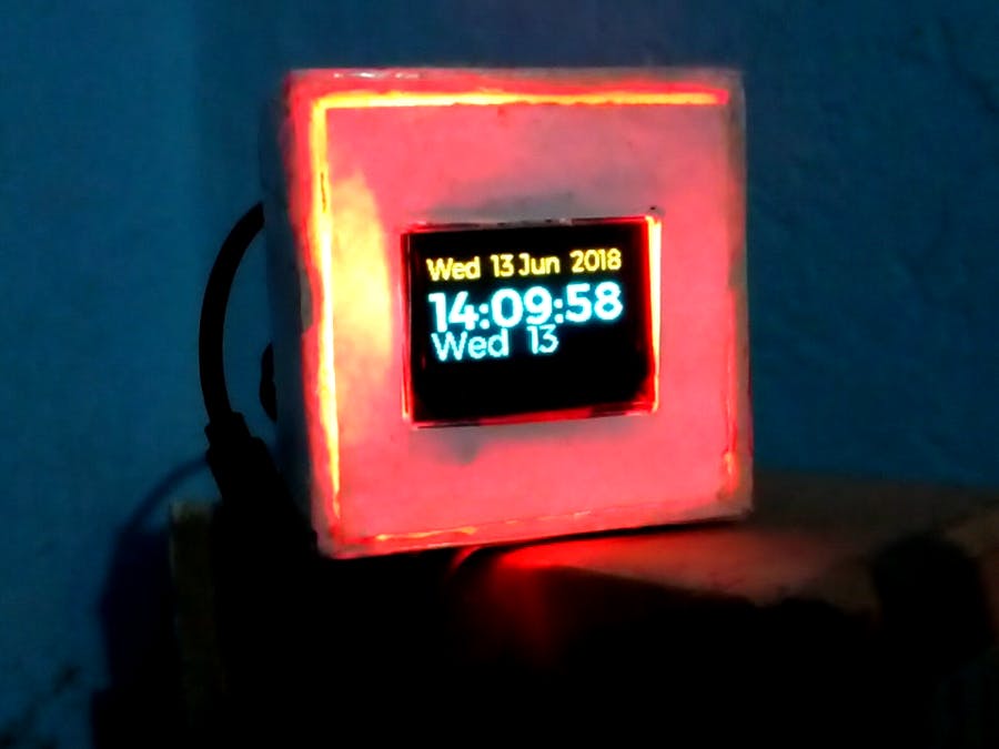
Want to build a smart clock with your Raspberry Pi that shows time on an OLED display? This project not only does that but also reads out the time to you at different intervals! All software configurations are done with Python.
Hardware & Software Needed
- Raspberry Pi 3 Model B
- RGB Diffused Common Cathode
- Speaker: 0.25W, 8 ohms
- Jumper Wires (Generic)
- Raspberry Pi OS on Raspberry Pi
- Python GPIO Library installed on the RPi
- Python SSD OLED Library
Interested to find out more? Visit the full tutorial with Python Code by Ashwini Kumr Sinha on Hackster!
2. Raspberry Pi Driven Robot Arm
This really cool project was developed by our Seeed R&D team. By using the 3D Gesture Tracking Shield that interfaces with the Raspberry Pi via its GPIO header, you can control a robot arm for picking up objects!
Hardware & Software Needed
- Raspberry Pi 3B+
- Seeed 3D Gesture & Tracking Shield for Raspberry Pi (MGC3130)
- Seeed uArm metal
- Raspberry Pi OS on Raspberry Pi
Want to learn more more? Check out the full tutorial by Seeed on Hackster!
3. Smart Raspberry Pi Fan Control
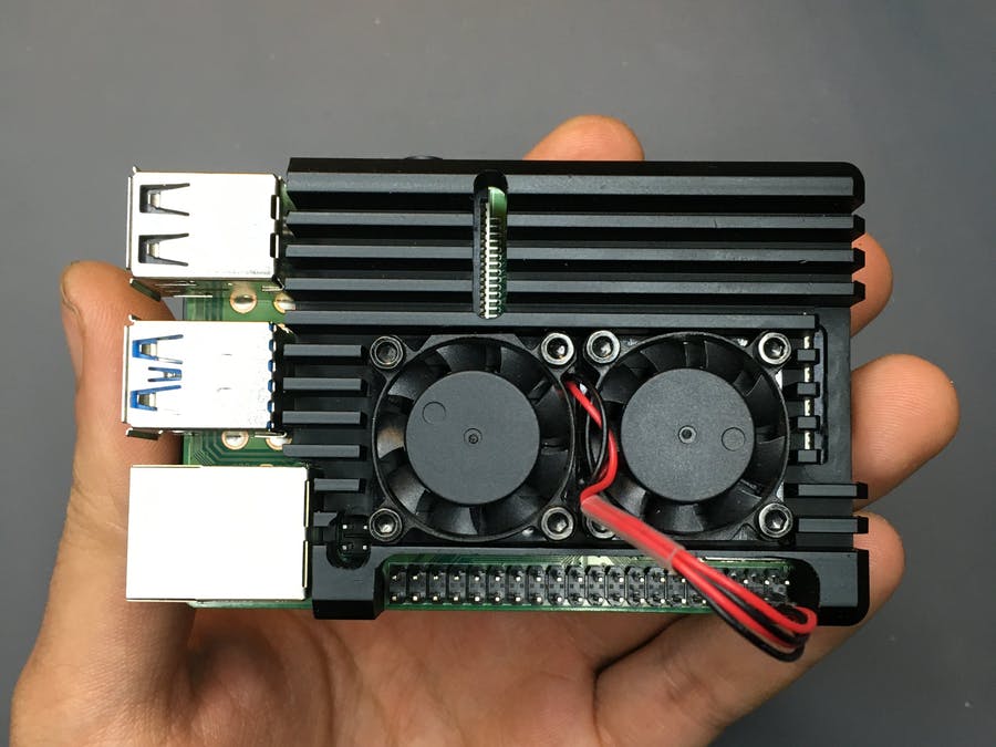
Worry about the thermal issues present in the Rasberry Pi 4, yet only want the fans to turn on when the processor really needs it? This project implements a Python script to adjust fan speeds based on the RPi’s CPU temperatures! Now you can cool your Raspberry Pi and learn Python at the same time!
Hardware & Software Needed
- Raspberry Pi 4 Computer Model B 4GB
- Seeed Armor Aluminum Metal Case with Dual Fans for Raspberry Pi
- General Purpose Transistor NPN
- Resistor 330 ohm
- Breadboard
- Jumper wires
- ThingSpeak API
Interested to find out more? You can check out the full tutorial by Nurgaliyev Shakhizat on Hackster!
Какие пины присутствуют на Raspberry Pi
У Raspberry распиновка включает в себя два ряда штырьков. Совокупное количество же пинов равняется 40, а значит в одном ряде их числов – 20.
В первую очередь человеку, который хочет подключить внешнее устройство, нужно знать, чем отличается каждый ряд. Первый (располагается слева) предназначается девайсам, для работы которых требуется напряжение в 3,3 Вольта. Второй (соответственно, размещается справа) – 5 Вольт. С этим не должно возникнуть вопросов.
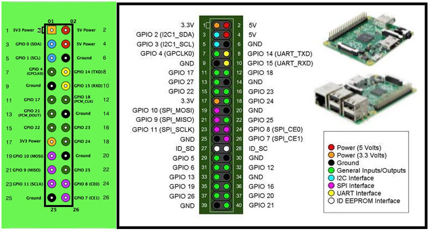
Следующее, что нужно знать о распиновке GPIO Raspberry Pi – назначение всех штырьков. Всего существует три типа пинов:
- питающие (при включении подают электричество);
- порты (выводящие и принимающие информацию);
- заземляющие.
Если посмотреть на схему Raspberry Pi 3 (или другой модели), то можно увидеть, что пины подписаны. Power – это питающие, Ground (иногда пишется GND) – заземляющие, а BCM – непосредственно порты.
Overview
As of Linux kernel 5.11, the old methods of communicating with header pins on the Raspberry Pi no longer work. This means packages such as RPi.GPIO no longer function properly with newer kernels. This post by Dave Jones (waveform) explains the reasons for the changes. But fear not, there is a new package in Ubuntu 21.04 called LGPIO that allows full control over the header pins with the latest kernel version. This tutorial covers some basic functionality of LGPIO, including examples using basic GPIO control, I²C, PWM, and SPI.
If you already have Ubuntu 21.04 or newer set up on a Raspberry Pi, you are ready for this tutorial. Otherwise, please see how to install Ubuntu Server on your Raspberry Pi and make it 21.04.
What you’ll learn
- How to install and get started with GPIO pins on Ubuntu
- Basic GPIO operations
- Basic I2C operations
- Basic PWM operations
What you’ll need
A Raspberry 3 or 4 with Ubuntu 21.04 setup and installed
Optionally for the examples:
- A simple breadboard
- 7x 330ohm resistors
- A single red, green or blue LED
- 10 male jumper wires
- 20 female to male jumper wires
- An Arduino Uno
- 5V PWM fan
- A RGB LED
- A rotary encoder
- An MCP3008 analog to digital converter
Управление GPIO «Малины» через Python
И теперь самое интересное: как выполняется управление GPIO Raspberry Pi через Пайтон.
Абсолютно отсутствует необходимость рассказывать о самом языке Python и подробно описывать библиотеку. Эту информацию легко найти на официальных сайтах соответствующих проектов – лучше изложить материал, чем там, крайне тяжело.
Однако есть смысл просто продемонстрировать некоторые принципы взаимодействия с GPIO. Конечно, перед написанием кода следует подключить устройство, с которым нужно работать к GPIO.
Первое, что потребуется сделать – это подключить библиотеку, делается это так: import PRi.GPIO as GPIO.
Далее нужно дать интерпретатору понять, что обращение к портам будет выполняться по их названиям. Это выполняется инструкцией: GPIO.setmode(GPIO.BCM). Предварительно также рекомендуется сбросить текущее состояние интерфейса (мало ли каково оно, хотя это и не критично) – GPIO.cleanup().
Далее можно сконфигурировать порты на выход и вход. Первое делается так: GPIO.setup(НОМЕР_ПОРТА, GPIO.OUT), а второе – GPIO.setup(НОМЕР_ПОРТА, GPIO.IN).
То есть, как можно убедиться, абсолютно ничего сложного в работе с GPIO нет. Главное – знать название портов (возможно почерпнуть из схемы) и функции, предусмотренные библиотекой.
Breadboard Basics
Let’s start with the breadboard.If it’s your first time with it, you may have a hard time understanding how it works.
Breadboard Installation
If you are using the breadboard kit I recommended above, the first step is to install it in the blue plastic case.Generally, you have to stick it in the large space and screw the Raspberry Pi to the corresponding location.
At this point your setup must look like this:
Don’t plug in the Raspberry Pi power cable for the moment.
Power Input
On the edges of the board, there are two lines:
- The red line is for the power input
- The blue line is for the ground
Each port is connected with all the pins from the same line.
Attention, with some breadboards (like mine), there is a separation in the middle, you can see a gap in the red line for example.If you plug near port 0, it will not work near port 50.
Other Ports
The other ports are used for everything else (LEDs, resistors, other modules).A wire connects them in columns.If you take one number on the board, it connects each port from the same column with the others.
Schema
It will be clearer with this picture:
I have squared each connected ports.
The red square corresponds to a power input line.There are four lines of this type on the board.If you input power in one of the squared ports, you can use it from any other highlighted ports.
For the ground ports it’s the same thing (blue square).
And for the other ports, you can see the green square how they are connected together.It’s the same for each column, for both side of the middle line.
If needed, here is a complete schema:
You may also like:
- 25 awesome Raspberry Pi project ideas at home
- 15 best operating systems for Raspberry Pi (with pictures)
- My book: Master your Raspberry Pi in 30 days
Writing the Python program to read the GPIO pin
With the circuit created we need to write the Python script that actually reads the state of the button and executes code based on the state.
Before we start writing the software we first need to install the Raspberry Pi GPIO Python module. This is a library that allows us to access the GPIO port directly from Python.
To install the Python library open a terminal and execute the following
$ sudo apt-get install python-rpi.gpio python3-rpi.gpio
With the library installed now open your favorite Python IDE (I recommend Thonny Python IDE more information about using it here).
Our initial script will initialize the GPIO port and then continuously read the status of the pin until we exit the program.
First we import the GPIO library and then setup the library to use board numbering. We then initialize pin 10 as an input pin, and instruct the Raspberry Pi to pull the pin low using the pull_up_down parameters.
The initialization code looks as follows:
import RPi.GPIO as GPIO # Import Raspberry Pi GPIO library

GPIO.setwarnings(False) # Ignore warning for now
GPIO.setmode(GPIO.BOARD) # Use physical pin numbering
GPIO.setup(10, GPIO.IN, pull_up_down=GPIO.PUD_DOWN) # Set pin 10 to be an input pin and set initial value to be pulled low (off)
The pull_up_down parameter in the GPIO.setup call tells the Raspberry Pi which state the pin should be in when there is nothing connected to the pin. This is important since we want our program to read a low state when the button is not pushed and a high state when the button is pushed.
With the port initialized we can write the code that continuously reads the port and outputs a message when the button is pressed. We use the GPIO.input function to read the state of the port.
while True: # Run forever
    if GPIO.input(10) == GPIO.HIGH:
        print("Button was pushed!")
We can now execute this program by saving it as push_button.py and running it either in Thonny or in the console as follows:
$ python3 push_button.py
You’ll notice that when you push the button the script outputs “Button was pushed!” many times. This is because we are continuously reading the state of the button. To get around this issue we can use a GPIO event. We will talk through how to do this in the next section.
If the program does not work, or continuously outputs “Button was pushed!” without the button being pressed down, try rotating the button 90 degrees.
Sysfs Example
As covered earlier in part 3 of this series, you can access GPIO pins through the file system using the sysfs interface. This is straightforward to do from C or C++. Here is an example program that toggles a GPIO pin every 100 milliseconds:
/*
Example of programming GPIO from C or C++ using the sysfs interface on
a Raspberry Pi.
Will toggle GPIO24 (physical pin 18) at a 100 millisecond rate for 10
seconds and then exit.
Jeff Tranter <<a href=»mailto:jtranter@ics.com»>jtranter@ics.com</a>>
*/#include <errno.h>#include <fcntl.h>#include <stdio.h>#include <stdlib.h>#include <sys/stat.h>#include <sys/types.h>#include <unistd.h>int main(){
// Export the desired pin by writing to /sys/class/gpio/export
int fd = open(«/sys/class/gpio/export», O_WRONLY);
if (fd == -1) {
perror(«Unable to open /sys/class/gpio/export»);
exit(1);
}
if (write(fd, «24», 2) != 2) {
perror(«Error writing to /sys/class/gpio/export»);
exit(1);
}
close(fd);
// Set the pin to be an output by writing «out» to /sys/class/gpio/gpio24/direction
fd = open(«/sys/class/gpio/gpio24/direction», O_WRONLY);
if (fd == -1) {
perror(«Unable to open /sys/class/gpio/gpio24/direction»);
exit(1);
}
if (write(fd, «out», 3) != 3) {
perror(«Error writing to /sys/class/gpio/gpio24/direction»);
exit(1);
}
close(fd);
fd = open(«/sys/class/gpio/gpio24/value», O_WRONLY);
if (fd == -1) {
perror(«Unable to open /sys/class/gpio/gpio24/value»);
exit(1);
}
// Toggle LED 50 ms on, 50ms off, 100 times (10 seconds)
for (int i = ; i < 100; i++) {
if (write(fd, «1», 1) != 1) {
perror(«Error writing to /sys/class/gpio/gpio24/value»);
exit(1);
}
usleep(50000);
if (write(fd, «0», 1) != 1) {
perror(«Error writing to /sys/class/gpio/gpio24/value»);
exit(1);
}
usleep(50000);
}
close(fd);
// Unexport the pin by writing to /sys/class/gpio/unexport
fd = open(«/sys/class/gpio/unexport», O_WRONLY);
if (fd == -1) {
perror(«Unable to open /sys/class/gpio/unexport»);
exit(1);
}
if (write(fd, «24», 2) != 2) {
perror(«Error writing to /sys/class/gpio/unexport»);
exit(1);
}
close(fd);
// And exit
return ;}
Note that if you want to try running this program, it is recommended to run it as root, otherwise you may run into file locking timing issues with udev that cause access errors.
I did some benchmarking of this example on a Raspberry Pi 3B. With delays removed, it would toggle the GPIO pin at a rate of about 350 kilohertz. This gives some idea of what can be done at this level of programming. Without using other programming tricks, there is no guarantee that the program won’t be periodically preempted to run other tasks.
The size of the binary when optimized and stripped was about 6K. and it had few dependencies on other shared libraries. This is several orders of magnitude smaller than Python, for example.
The Raspberry Pi also has hardware support for PWM on some pins, and other features that can help optimize programs like this, and there are other performance optimization techniques like direct GPIO register access. We may look at this in a future post.
Python (RPi.GPIO) API
We’ll use the RPi.GPIO module as the driving force behind our Python examples. This set of Python files and source is included with Raspbian, so assuming you’re running that most popular Linux distribution, you don’t need to download anything to get started.
On this page we’ll provide an overview of the basic function calls you can make using this module.
Setup Stuff
In order to us RPi.GPIO throughout the rest of your Python script, you need to put this statement at the top of your file:
That statement «includes» the RPi.GPIO module, and goes a step further by providing a local name — — which we’ll call to reference the module from here on.
Pin Numbering Declaration
After you’ve included the RPi.GPIO module, the next step is to determine which of the two pin-numbering schemes you want to use:
- — Board numbering scheme. The pin numbers follow the pin numbers on header P1.
- — Broadcom chip-specific pin numbers. These pin numbers follow the lower-level numbering system defined by the Raspberry Pi’s Broadcom-chip brain.
If you’re using the Pi Wedge, we recommend using the definition — those are the numbers silkscreened on the PCB. The may be easier if you’re wiring directly to the header.
To specify in your code which number-system is being used, use the function. For example…
…will activate the Broadcom-chip specific pin numbers.
Both the and lines of code are required, if you want to use Python.
Setting a Pin Mode
If you’ve used Arduino, you’re probably familiar with the fact that you have to declare a «pin mode» before you can use it as either an input or output. To set a pin mode, use the function. So, if you want to set pin 18 as an output, for example, write:
Remember that the pin number will change if you’re using the board numbering system (instead of 18, it’d be 12).
Outputs
Digital Output
To write a pin high or low, use the function. For example, if you want to set pin 18 high, write:
Writing a pin to will drive it to 3.3V, and will set it to 0V. For the lazy, alternative to and , you can use either , , or to set a pin value.
PWM («Analog») Output
PWM on the Raspberry Pi is about as limited as can be — one, single pin is capable of it: 18 (i.e. board pin 12).
To initialize PWM, use function. To make the rest of your script-writing easier you can assign that instance to a variable. Then use function to set an initial value. For example…
…will set our PWM pin up with a frequency of 1kHz, and set that output to a 50% duty cycle.
To adjust the value of the PWM output, use the function. can be any value between 0 (i.e 0%/LOW) and 100 (ie.e 100%/HIGH). So to set a pin to 75% on, for example, you could write:
To turn PWM on that pin off, use the command.
Simple enough! Just don’t forget to set the pin as an output before you use it for PWM.
Inputs
If a pin is configured as an input, you can use the function to read its value. The function will return either a or indicating whether the pin is HIGH or LOW. You can use an statement to test this, for example…
…will read pin 17 and print whether it’s being read as HIGH or LOW.
Pull-Up/Down Resistors
Remember back to the function where we declared whether a pin was an input or output? There’s an optional third parameter to that function, which you can use to set pull-up or pull-down resistors. To use a pull-up resistor on a pin, add as a third parameter in . Or, if you need a pull-down resistor, instead use .
For example, to use a pull-up resistor on GPIO 17, write this into your setup:
If nothing is declared in that third value, both pull-resistors will be disabled.
Etc.
Delays
If you need to slow your Python script down, you can add delays. To incorporate delays into your script, you’ll need to include another module: . This line, at the top of your script, will do it for you:
Then, throughout the rest of your script, you can use to give your script a rest. You can use decimals to precisely set your delay. For example, to delay 250 milliseconds, write:
The time module includes all sorts of useful functions, on top of . Check out the reference here.
Garbage Collecting
Once your script has run its course, be kind to the next process that might use your GPIOs by cleaning up after yourself. Use the command at the end of your script to release any resources your script may be using.
Your Pi will survive if you forget to add this command, but it is good practice to include wherever you can.