Installation
Linux
Debian repository
Go to download
repository
- Download GPG key:
wget -c
http://download.opensuse.org/repositories/home:/ra3xdh/Debian_9.0/Release.key - Add the following line to /etc/apt/sources.list:
deb http://download.opensuse.org/repositories/home:/ra3xdh/Debian_9.0/ ./ - Import key and update repos:
apt-key add Release.key
apt-get update - Install Qucs-S
apt-get install qucs-s
*.debdpkg
dpkg -i qucs-s-0.0.19S_amd64.deb
You may need to install the following dependencies: lib4qt4-qt3support,
ibqt4-svg, ngspice
RPM packages for CentOS and Fedora
You need to simple add reposotries using the yum package manager. Let’s consider
example for CentOS:
- First add repository
yum-config-manager --add-repo http://download.opensuse.org/repositories/home:/ra3xdh/CentOS_7/
yum-config-manager --enable ra3xdh - Then check that repository is added
yum repolist alll
-
And finally install the qucs-s package
yum install qucs-s
Building from source
- Install all necessary dependencies: Qt, C++ compilers, etc.
- Install desired simulation backends: Ngspice, XYCE, SpiceOpus. You can use all
these backends together or only one of them. Install basic Qucs (0.0.18 or
newer) if Qucsator is needed. - Download and unpack tarball
- Use CMake to compile. Autotools doesn’t support this installation mode and
will not work! - Invoke make and make install
tar xvfz qucs-s-0.0.21.tar.gz
cd qucs-s-0.0.21
mkdir builddir
cd builddir
cmake ..
make
make install
The last command make install should be executed from root user. It will
install Qucs-S into default prefix /usr/local/. Use -DCMAKE_INSTALL_PREFIX=...
to override the default locationNo additional configure options are needed now.
Slackware SlackBuild
- Clone this repository:
git clone https://github.com/ra3xdh/QucsS.SlackBuild - Run SlackBuild as root:
cd QucsS.S.SlackBuild
./qucs-S.SlackBuild - Install txz package with installpkg command
Windows
http://ngspice.org/https://xyce.sandia.gov
Important note for Ngspice on Windows: Unpack Ngspice ZIP package strictly to the
C:\SPICE location. Otherwise XSPICE model will not work! If you are getting strange errors with Ngspice
on Windows and cannot ot simulate even simple circuit, please check that Ngspice is installed strictly in
C:\SPICE . All Ngspice packages including offcial should be installed in a such way.
It’s recommended special build of Ngspice-26 for Windows
Ngspice26_QucsS.zip
. Default Ngspice package also will work but it may have some limitation. Custom
Ngspice build solves the following issues:
- Windows GUI of Ngspice is disabled. It allows Qucs-S to obtain logs from
Ngspice. - Added CMPP preprocessor and C headers set mandatory for development of
CodeModel libraries. Default Ngspice build is shipped without it.
Spice4qucs subcircuits with parameters
Subcircuits which have component or physical parameter values set by a list of names and values attached to a schematic symbol add a significant “value added”
feature to the subcircuit concept. This form of subcircuit can, for example, be used to represent manufacturers product variations which have identical circuits but
require component values or device parameter values of differing value. Unfortunately, SPICE 3f5 only implements subcircuits without parameters.
Recent generations of open-source GPL circuit simulators, including Ngspice, Xyce and SPICE OPUS, have been extended by their Development Teams to allow subcircuits with parameters.
One consequence of this is that over time divergence of the SPICE subcircuit statement syntax has occurred amongst different circuit simulators.
implements a common subset of the published extended SPICE subcircuit syntax. This works well, but does have one disadvantage however, in that some published subcircuit netlists may require a small amount of editing before they will simulate with . One code word often found in the SPICE extended subcircuit syntax is the term PARAMS:. This can occur in an X subcircuit call to
signify a subcircuit with parameters. As this is optional in Ngspice, and indeed in other SPICE derived circuit simulators, it is not implemented in .
Qucsator, Ngspice, Xyce and SPICEOPUS all allow parameters to be attached to subcircuit symbols and to be used in design equation calculations.
As an introductory example Figure 3.6 illustrates a circuit schematic and user generated symbol for a simple Qucs harmonic generator composed of a fundamental AC signal and three sinusoidal harmonic components. Parameters \(f1\) to \(f4\) set the frequencies of the harmonics. The Qucs Equation block, at the subcircuit internal circuit level, is used to calculate the individual harmonic frequencies. In a similar fashion \(ph1\) to \(ph4\) represent the phases of the signal harmonics.
Figure 3.6 Qucs subcircuit sinusoidal harmonic signal generator: \(f1\) is the fundamental frequency and \(f2\) to \(f4\) the higher order harmonics;
\(ph1\) to \(ph4\) the phases of the fundamental signal and its harmonics. For clarity long Qucs netlist lines have been spread over more than one line.
Figure 3.7 Ngspice subcircuit sinusoidal harmonic signal generator.
Figure 3.7 shows an Ngspice version of the Qucs sinusoidal harmonic generator illustrated in Figure 3.6. A casual look at these two subcircuit diagrams shows that they are not dissimilar.
However, there are a number of subtle changes apparent from the diagrams. First it is important to realise that the Qucs and SPICE sinusoidal (sin) signal generator specifications are different;
Qucs requires the signal phase and SPICE the signal delay to be specified as parameters. In Figure 3.7 extra equations to convert phase to time delay are added to Equation block Eqn1 inside subcircuit SPICEHarmonicGen.
To ensure that Eqn1 variables, for example frequency \(f2\), are passed to the subcircuit component values as numerical values SPICE curly deliminator brackets, {…}, are placed round equation variable names. Finally, it is important to realize that the order of the variables in Equation blocks are important. Qucs allows them to be in any order because it arranges all entries into a sequence which ensures each variable can be allocated a numerical value before it is used in other equations. However, SPICE does not do the same but assumes
that all variables included in the right hand side of an equation have been allocated a numerical value prior to being used in the calculation of the variable named on the left hand side of the same equation.
To check that the Ngspice generated waveform is correctly generated a Fourier analysis of signal \(V(ngensig)\) is displayed on Figure 3.7. At frequencies above \(f4\) the phase values have no meaning.
The simulated signal waveform obtained with SPICE OPUS was found to be similar to that obtained with NGSPICE, see Figue 3.8. Try simulating the sinusoidal harmonic generator waveform with SPICE OPUS to check this statement for your self.
Функции из электроники
Преобразование единиц измерения
| dB(x) |
Значение в дБ |
| dbm(x) |
Преобразовать напряжение в мощность в дБм |
| dbm2w(x) |
Преобразовать мощность в дБм в мощность в ваттах |
| w2dbm(x) |
Преобразовать мощность в ваттах в мощность в дБм |
| vt(t) |
Температурный потенциал для данной температуры t в градусах Кельвина |
Коэффициенты отражения и КСВН
| rtoswr(x) |
Преобразует коэффициент отражения в коэффициент стоячей волны по напряжению (КСВН) |
| rtoy(x) |
Преобразует коэффициент отражения в полную проводимость; по умолчанию zref равно 50 Ом |
| rtoz(x) |
Преобразует коэффициент отражения в полное сопротивление; по умолчанию zref равно 50 Ом |
| ytor(x) |
Преобразует полную проводимость в коэффициент отражения; по умолчанию zref равно 50 Ом |
| ztor(x) |
Преобразует полное сопротивление в коэффициент отражения; по умолчанию zref равно 50 Ом |
N-портовые матричные преобразования
| stos(s,zref) |
Преобразует матрицу S-параметров в матрицу S-параметров с другим эталонным полным сопротивлением(ями) |
| stoy(s) |
Преобразует матрицу S-параметров в матрицу Y-параметров |
| stoz(s) |
Преобразует матрицу S-параметров в матрицу Z-параметров |
| twoport(m,from,to) |
Преобразует двух-портовую матрицу из одного представления в другое, возможные значения для from и to равны ‘Y’, ‘Z’, ‘H’, ‘G’, ‘A’, ‘S’ и ‘T’. |
| ytos(y) |
Преобразует матрицу Y-параметров в матрицу S-параметров |
| ytoz(y) |
Преобразует матрицу Y-параметров в матрицу Z-параметров |
| ztos(z) |
Преобразует матрицу Z-параметров в матрицу S-параметров |
| ztoy(z) |
Преобразует матрицу Z-параметров в матрицу Y-параметров |
A second more complex example of Spice4qucs subcircuits with parameters
Variable assignment equations, defined in Qucs Equation Eqn
blocks and embedded in a subcircuit, are converted by
into SPICE statements. These are listed in the initial section of the SPICE-netlist of the circuit being simulated, or in the first section of a subcircuit netlist, allowing their values to be determined before the start of a simulation.
With Qucs Equation Eqn blocks it is important to remember that the variables defined cannot be functions of circuit voltage or current or any other voltage/current dependent properties.
Restrictions placed by on the use of Qucs Equation Eqn blocks are considered in detail in Chapter 4. However, one fundamental rule that must be followed at all
times is that Qucs simulation icons must not be placed inside a subcircuit.
The electrical equivalent circuit of a HC-49/U 8.86 MHz Quartz crystal resonator is shown in Figure 3.9.
In this model the crystal resonator is represented as the RCL parallel electric network illustrated in
the following two schematics:
- — Quartz crystal resonator subcircuit; Figure 3.9.
- — test circuit; Figure 3.10.
These files can be found in the Qucs-S subdirectory .
Figure 3.9 shows the crystal resonator subcircuit. A brief introduction to the theory of crystal resonators can be found at https://en.wikipedia.org/wiki/Crystal_oscillator.
Figure 3.9 Equivalent circuit of Quartz crystal resonator.
In the HC-49/U Quartz crystal resonator model the \(RCL\) network has two resonant frequencies:
a series resonance frequency \(f\), where
\
and a parallel resonance frequency \(f_{p}\), where
\
Transposing equation \(f\) yields an expression for the series capacitance \(C_q\), where
\
This equation is placed in Qucs Equation Eqn1 block inside the Quartz crystal resonator subcircuit.
Performing an AC simulation with Ngspice and Xyce, using the test circuit given in Figure 3.10, yields the amplitude response data plotted in Figure 3.11,
Ngspice transfer coefficient () and Xyce voltage .
Figure 3.10 Test circuit for Quartz crystal resonator.
Figure 3.11 indicates that the Ngspice and Xyce plotted results are identical.
The only difference being that Xyce simulation result postprocessing is not implemented.
Hence, only the Xyce output voltage can be plotted; this is done by choosing a logarithmic Y scale, then the Xyce plot
effectively displays a scaled decibel output. The two resonant frequencies \(f\) and \(f_p\) are clearly visible on these plots.
Figure 3.11 Magnitude response of HC-49/U Quartz crystal.
Subcircuits are converted by into SPICE routines. The SPICE netlist for the Quartz crystal resonator test
circuit, Figure 3.10, shown below illustrates how the handles SPICE , and subcircuit call statements,
placing them in the correct position within the SPICE netlist of the circuit being simulated.
Интерфейс программы Multisim
Начнем с изучения интерфейса программы.
Основные функциональные панели программы показаны на следующем рисунке.
Отдельный интерес представляет панель компонентов. С помощью панели компонентов осуществляется доступ к базе компонентов. При нажатии на любую из выбранных пиктограмм компонентов схем открывается окно Выбор компонента. В левой части окна осуществляется выбор необходимого компонента.
Вся база данных компонентов разделена на разделы (пассивные элементы, диоды, транзисторы, микросхемы и т. д.), а разделы на семейства (например, для диодов – это сами диоды, стабилитроны, светодиоды, тиристоры и т. д.). Надеюсь идея понятна.
Так же в окне выбора компонента можно посмотреть обозначение выбранного компонента, описание его функции, выбрать тип корпуса.
Symbol pattern files format description
Let’s consider symbol files format. Symbols have extension and are
placed in subdirectory of the Qucs installation tree.
Qucs automatically scans content of this subdirectory and displays all found
valid symbols in drop-down list in the third property () of the
SpiceLibComp device. User can select any symbol for new SPICE library device.
It’s need to create a new symbol file and place it into symbols directory to add
new symbols to the existing Qucs installation.
Let’s consider symbol file format. Symbols have Qucs XML schematic format
without header. An example of symbol file (five-terminal opamp) is shown in the
listing below:
1 2 3 4 5 6 7 8 9 10 11 12 13 14 15 16 17 18 19 |
<Symbol> <Line -20 -40 0 80 #000080 2 1> <Line -20 -40 60 40 #000080 2 1> <Line -20 40 60 -40 #000080 2 1> <Line 40 0 20 0 #000080 2 1> <Line -40 -20 20 0 #000080 2 1> <Line -40 20 20 0 #000080 2 1> <Line -15 20 10 0 #000000 2 1> <Line -10 -25 0 10 #ff0000 0 1> <Line -15 -20 10 0 #ff0000 0 1> <Line 10 -20 0 -20 #000080 2 1> <Line 10 20 0 20 #000080 2 1> <.PortSym 10 40 4 0> <.PortSym 10 -40 3 0> <.PortSym -40 20 2 0> <.PortSym -40 -20 1 0> <.PortSym 60 0 5 180> <.ID 30 24 OP> </Symbol> |
Automatic symbol files preparation is not yet implemented, but you can use Qucs
schematic editor to create new symbol files. You may use the following sequence
to create new symbol:
- Create Qucs subcircuit. Subcircuit may be empty. Place desired ports on it;
- Attach symbol to it using switching to symbol mode by keystroke. Wire
subcircuit ports to symbol and paint symbol outline. - Save subcircuit, open it with any test editor and copy-paste symbol code form it
into the symbol file.
Please pay attention to the proper port mapping. Let’s consider port definition
line format:
<.PortSym 10 -40 3 0>
This port definition consists of five space separated fields. The fourth field
() contains port number. This port number should match SPICE
port number (not port name!) to proper component wiring. You may need to edit
this field manually.
For example AD822 has the following definition in our library:
.SUBCKT AD822 1 2 99 50 25
Subcircuit node list follows after the subcircuit name ( ). Subcircuit
nodes will be mapped to component port in the following sequence:
2.10.2 DC Example 2: Variation of power dissipation with varying DC input voltage.
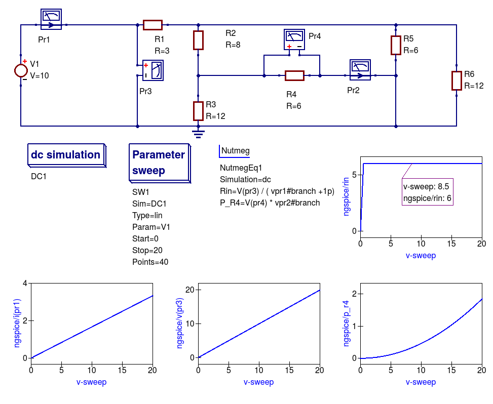
Figure 2.12 DC example 1 with varying DC input voltage: demonstrating the use of a DC sweep simulation.
- Draw the circuit diagram shown in Figure 2.11,
- Select simulator Ngspice,
- Add the dc simulation, Parameter sweep and Nutmeg component icons to the drawn schematic,
- Complete the Parameter sweep and Nutmeg component data entries so that they are the same as given in Figure 2.11,
- Press the F2 to simulate the circuit,
- Plot the graphs illustrated in Figure 2.11,
- Check that your results are the same — if not or the simulation fails check your schematic for errors and re-simulate.
Notes:
- Current probe values are represented by the SPICE 3f5 notation: vpr1#branch and vpr2#branch.
- There is a discontinuity in Rin when the vpr1#branch current is zero Amperes; hence the need for the dummy 1pA in the Nutmeg equation for Rin.
5.6 Spectrum analysis with Ngspice and Nutmeg scripting
Qucs-S have no unified simulation type “Spectrum analysis” for all simulation
backends. But you may use Nutmeg scripting to implement Spectrum analysis if
Ngspice or SpiceOpus is selected as the default simulation kernel.
Let’s consider double balanced passive diode mixer circuit.
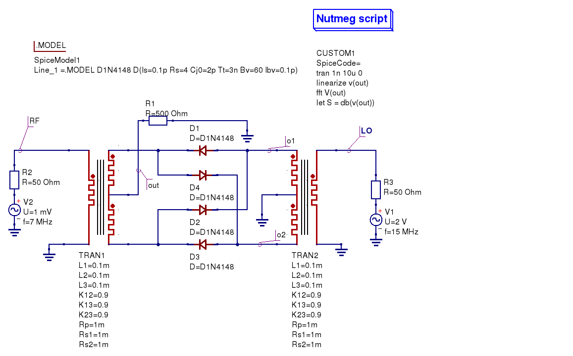
Figure 5.8 Diode double balanced mixer simulation
Balanced mixer circuit has two inputs: local oscillator
\(f_{LO}=15\mathrm{MHz}\) ( node) and RF signal \(f_{RF}=7\mathrm{MHz}\)
( node on schematic) and gives a set of signals at the outputs. Transformer
models are taken from the Transformer library form the Qucs-S distribution.
Output signal is taken from the node. It contains components with the
following frequencies:
\
The following two components are the strongest (upper IF and lower IF
respectively):
\
\
We should see these signals as peaks at the spectrum plot.
We want to obtain mixer output voltage plot . It’s need to use Nutmeg
scripting to obtain the spectrum. Nutmeg script component serves for this
purpose at the presented circuit. Let’s consider Nutmeg script structure. Such
structure is need to be used for every spectrum analysis. Nutmeg script source
code is presented here:
1 2 3 4 |
tran 1n 10u linearize v(out) fft V(out) let S = db(v(out)) |
Spectrum calculation is performed by the operator at the line #3.
The argument of this function is transient simulation result vector (voltage or
current). And it’s need to perform a transient simulation before.
Transient simulation is performed at the line #1. Simulation step is \(t_s=1\mathrm{ns}\)
and duration is \(T_d=10\mathrm{\mu s}\). This gives
\
spectrum points.
Frequency step will be:
\
We can summarize that the smallest timestep and the longest duration gives the
most precise frequency step and spectrum analysis precision. But it increases
the simulation time.
Ngspice uses dynamic timestep calculation at simulation time. And real timestep
may differ from the specified in the statement. It’s need to perform
simulation analysis linearization. Line#2 linearizes simulation result (output
voltage ). Vector contains now linearized transient simulation
result and could be passed to the input (line #3).
After FFT we can plot vector and see spectrum. But we can apply any
postprocessing to it. For example we can express spectrum in decibels (dB) with
nutmeg function (line #4, variable). You need to specify these
two variables in the Nutmeg script properties (Figure 5.9)
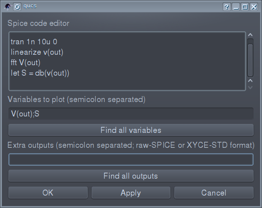
Figure 5.9 Nutmeg script properties setup
Simulation results are shown in the Figure 5.10. Both spectrum and logarithmic
spectrum (dB) are shown.
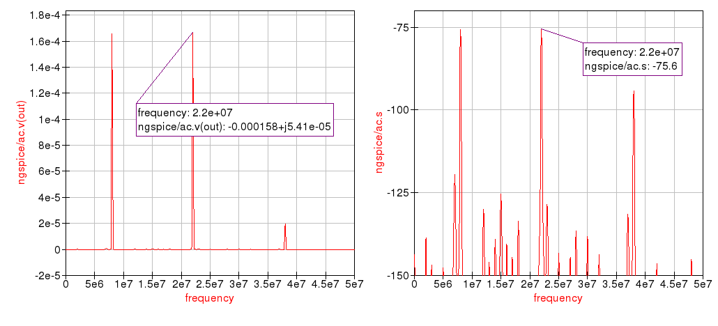
Figure 5.10 Spectrum simulation result.
We can see two main peak on spectrum (\(f_{IF1}=22 \mathrm{MHz}\) and \(f_{IF2}=8\mathrm{MHz}\)
respectively). RF and LO signals are rejected.
Spice4qucs subcircuits without parameters
Figure 3.1 shows a Qucs subcircuit model for a 15MHz centre frequency band pass passive filter. Note that the three
distinct parts of a subcircuit model without parameters are: (1) a circuit representing the model body with one or more input (Pin) and output (Pout) pins plus
connected components selected from Qucs pre-defined components and user designed subcircuits ( there are no user defined subcircuits present in Figure 3.1),
(2) a subcircuit symbol, and (3) a Qucs netlist giving a list of the internal components, their connection nodes and a wrapper which
defines the subcircuit. The syntax of the subcircuit netlist listed in Figure 3.1 is only understood by Qucs and cannot be read without error by external SPICE simulators.
Figure 3.1 Qucs 15MHz centre frequency band pass passive filter subcircuit without parameters
A test bench circuit for simulating the band pass filter circuit shown in Figure 3.1 is given in Figure 3.2. This figure includes a plot of the small signal AC
output voltage for a filter with 50 Ohm input and output matching resistors. Note the use of a node voltage probe and the signal name allocated by
Qucs. Also note that the individual
capacitor voltage and inductor current initial conditions are not set as they are not needed due to fact that the filter subcircuit is not DC biased. As a consequence
the DC simulation icon shown in Figure 3.2 is not strictly necessary. However, its a good idea to add it automatically to AC simulations because circuits with
semiconductor devices or other non-linear components must have their small signal AC properties calculated, at their DC bias conditions, prior to small signal AC simulation.
Figure 3.2 Qucs 15MHz centre frequency band pass passive filter test bench with 50 Ohm source and load matching
Figure 3.3 to Figure 3.5 present AC simulation results for the band pass filter generated with the Ngspice, Xyce and SPICEOPUS circuit simulators.
Figure 3.3 Band pass filter Ngspice test results and SPICE netlist for test bench circuit.
Figure 3.4 Band pass filter Xyce test results and SPICE netlist for test bench circuit.
Figure 3.5 Band pass filter SPICEOPUS test results and SPICE netlist for test bench circuit.
Симулятор или эмулятор Arduino?
Давайте сразу договоримся, что в статье мы будем использовать оба этих термина, хотя их значение вовсе не идентично. Симулятором называют устройство или сервис, имитирующие определенные функции другой системы, но не претендующим на создание точной копии. Это некоторая виртуальная среда, в которой мы просто моделируем другую систему. Эмулятор – это полноценный аналог, способный заменить оригинал. Например, Tinkercad симулирует работу электронных схем и контроллера, но при этом он является эмулятором ардуино, реализуя практически все базовые функции Arduino IDE – от среды редактирования и компилятора до монитора порта и подключения библиотек.
С помощью этого класса программ можно не только рисовать электронные схемы, но и виртуально подключать их к электрической цепи с помощью встроенного симулятора. В режиме реального времени можно наблюдать за поведением схемы, проверять и отлаживать ее работоспособность. Если в такой симулятор добавить виртуальнyю плату Arduino, то можно отследить поведение схемы и в ардуино-проектах. Для отладки скетчей во многих известных сервисах присутствует также возможность загрузки настоящих скетчей, которые “загружаются” в модель и заставляют вести схему с подключенными элементами так же, как и со включенной реальной платой. Таким образом, мы сможем эмулировать работу достаточно сложных проектов без физического подключения Arduino, что существенно ускоряет разработку.
13.4 Single tone large signal AC Harmonic Balance simulation
The Spice4qucs subsystem supports Xyce single tone and multi-tone Harmonic Balance (HB).
Unlike the rudimentary version of HB simulation implemented in Qucs the Xyce version can simulate circuits
with a full range of SPICE components. It is also faster and much more stable. In general no changes to the SPICE
semiconductor device or component models are required. To invoke single tone HB just place
the Qucs-S icon on a circuit schematic, define the number of harmonics and
simulate the circuit with Xyce. The spice4qucs output data parser automatically converts output variable names to Qucs notation.
For example, for node voltage plot .
Figure 13.6 shows the schematic and Figure 13.7 the simulation output plots for a basic diode circuit similar to the original Qucs HB example found
on the Qucs web site. For comparison Figure 13.7 presents the output voltage spectrum plots generated by Qucs and Qucs-S/Xyce.
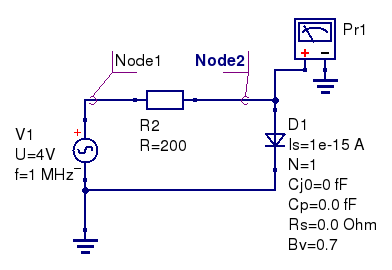
Figure 13.6 Diode clipper harmonic balance simulation.
The HB simulation results for the diode clipper circuit are shown in the Figure 13.7.
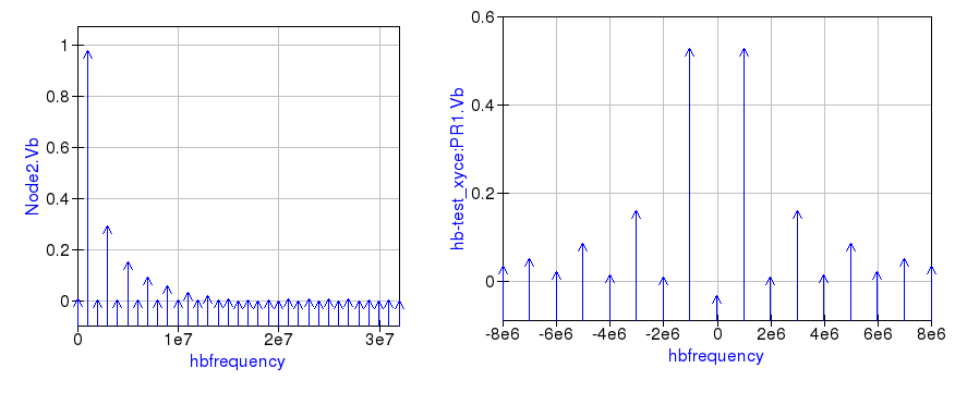
Figure 13.7 Output voltage spectrum at Node2 for Qucs (left plot), and measured with voltage probe Pr1 for Xyce (right plot).
Comparing these two plots highlights an obvious difference in the plot frequency scales.
The Qucs-S/Xyce output plot is represented as a function of negative and positive frequency components.
In this example there are eight harmonics () arranged as 8 positive frequencies and eight
negative frequencies plus a DC component.
Qucs HB simulation data are output as a plot of frequency domain spectral amplitude components \(|H|\), where
\
\(U(0)\) is the DC spectral component, \(U(f_n)\) is the magnitude of a harmonic component at frequency \(f_n\) and \(n=1, 2, 3, 4,…\).
In contrast to Qucs, Xyce outputs HB voltage and current simulation data as plots of complex conjugate spectral components, where
\
2.4 Variable names
As part of the extensions Ngspice and Xyce simulation variable names are converted from Qucs
notation to SPICE notation and vica versa. Table 2.1 shows the correspondence between the two notations.
Table 2.1 Qucs and SPICE variable equivalences
| Variable type | Qucs display notation | Spice display notation |
|---|---|---|
| DC node voltage | Node.V | V(node) |
| AC node voltage | Node.v | ac.v(node) |
| TRAN node voltage | Node.Vt | tran.v(node) |
| HB node voltage | Node.Vb | hb.v(node) |
| DC probe current | Pr1.I | i(pr1) |
| AC probe current | Pr1.i | ac.i(pr1) |
| TRAN probe current | Pr1.It | tran.i(pr1) |
Also variable prefixes used to designate data from different simulators (Table
2.2)
Table 2.2 Qucs and SPICE variable name prefixes
Frequently Asked Questions
-
How should I speak the word Qucs?
The correct pronunciation is kjuks.
-
What is the best way to get started with QucsStudio?
1) Watch the videos on this homepage.
2) Read the program help (F1 key) and the tutorial by Gunthard Kraus.
3) Test the example schematics from this homepage.
4) Modify the examples according to your needs.
5) Ask your remaining questions in the forum.
-
Why are there two different projects: Qucs and QucsStudio?
This situation isn’t nice indeed. But at some point it wasn’t possible
anymore to reach an agreement about future developments.
That’s why I left the Qucs project. After some time I went on programming
on my own and QucsStudio was born.
-
What are the differences between Qucs, Qucs-S and QucsStudio?Qucs is the original project,
which all others based on. The program is open-source and available for
Linux, Windows and MacOS. But it’s now rarely updated, so very few progress
can be expected only.Qucs-S is a Qucs fork.
It’s open-source and available for Linux and Windows. The graphical interface
supports the simulators
Qucs,
Ngspice,
XYCE and
SpiceOpus.
Again, updates are to be expected rarely.QucsStudio is a Qucs fork
that stems from the original project founder. It’s freely available for
Windows and not open-source. But it offers by far the most features
and is updated regularly.fREEDA is another open-source
simulator that uses the graphical user interface of Qucs. The last update
of this project was in November 2010.
-
How does the future of QucsStudio look like?
QucsStudio will continue to be freely available.
An open-source version is not planned.
-
Why does it take so long until a new version is released?
QucsStudio is a purely private project. Thus, there’s not much time
for the development. Unfortunately, support by users is very rare, too.
Any help will speed up the progress!
-
I don’t want all the data to be saved in .qucs\ in the
user directory. How can I change this?
The wanted directory can be set with a minus sign in the command line,
e.g. running qucs.exe -«C:/projects».
A file link is the best way to
realize this. I.e. drag’n’drop qucs.exe onto the desktop
by pressing the Alt key. Then click with the right-hand mouse button
onto this icon and choose Properties in the opening menu.
In the appearing dialog the command line can be entered.
Having this done, QucsStudio can be started with the new directory
by double-clicking on this link.
-
Does QucsStudio run on other operating systems than Windows?
With the software Wine,
Windows applications like QucsStudio runs on Linux, MacOS and BSD.
This was successfully tested many times.
If simulations with microstrip components end up with an error message
(about sinh function), the wrong DLLs are used. Then, start winecfg.
In the Library tab add msvcp100 and msvcr100 and set them
to native.
-
What should I do if my question isn’t answered here?
Please have a look into the forum.
A lot of topics have already been discussed there.
And of course, you can also ask your own questions.