Введение
Предполагается, что вы уже справились с установкой и активацией LabVIEW NXG.
Основное отличие от имеющихся учебных материалов будет заключаться в том, что мы будем изучать этот язык с точки зрения средства разработки «общего назначения». В процессе изложения я буду пытаться также проводить параллели с текстовыми языками чтобы показать некоторые отличия от «традиционных» средств разработки. Для иллюстрации я буду использовать C# (в минимальном варианте, доступном и тем, кто понимает базовый синтаксис языка С). Изложение будет настолько подробным, насколько возможно, по мере углубления в дебри LabVIEW степень «подробности» основ будет уменьшаться. Также потребуется минимальное знание английского — русской локализации LabVIEW пока нет.
Итак, LabVIEW программа собирается из отдельных «кирпичиков», которые называются «Виртуальные Инструменты» («Virtual Instruments») или коротко VI. Первые версии LabVIEW предназначались для превращения ПК в измерительный прибор-инструмент, так что исторически за ними и закрепилось такое вот название. Также как С# программа собирается из отдельных *.cs файлов, также и LabVIEW программа собирается из VI файлов (в классической LabVIEW 2020 у них расширение *.vi, а в NXG — *.gvi). Множественные файлы объединяются в проекты. Единственное отличие — представьте себе, что вы организуете проект таким образом, что в каждом файле лежит только одна функция (ну или метод класса, если будет угодно). В небольшом проекте счёт отдельных виртуальных инструментов может идти на десятки, в проектах средних размеров — на сотни, а в больших проектах — тысячи их (предполагается, что размер кода в каждом отдельном инструменте находится в пределах разумного). Вот сейчас я работаю над проектом, в котором семь с лишним тысяч VI и это довольно большой проект.
При первом запуске LabVIEW NXG покажет нам вот такое окно:
Здесь перечислены шесть основных направлений, в которых применяется LabVIEW. В принципе без разницы, что вы здесь выберете, просто для некоторых направлений разработки или обучения нам рекомендуется «классическая» LabVIEW, а для некоторых — NXG, поскольку функциональность NXG пока проигрывает классической LabVIEW, но команда NI работает в этом направлении, а нам для изучения и NXG хватит с лихвой.
На этот вопрос нужно ответить всего один раз, после этого NXG будет запускаться вот так:
Project Sublibraries
Project sublibraries are project libraries that another project library owns. The settings in the owning project library do not affect access settings and editing permission for items within the project sublibrary. You can set the access of a project sublibrary file (.lvlib) as private within the owning project library, but when you edit the project sublibrary itself, items the sublibrary owns retain public or private access settings.
Project sublibraries are useful if you want to create a project library that includes separate areas of functionality. For example, if you are creating a project library of graphics tools, you might divide the two-dimensional and three-dimensional drawing tools into separate sublibraries.
Locating Missing SubVIs, Palettes, and Property Nodes (macOS)
|
LabVIEW may not be able to locate certain subVIs, palettes, or Property Nodes for the following reasons:
|
Diagnosing Common LabVIEW Launch Errors (Linux)
Launch errors on 64-bit systems—If LabVIEW fails to launch on a 64-bit Linux system, verify that you have installed the 32-bit compatibility libraries for your distribution. |
Locating Missing SubVIs, Palettes, and Property Nodes (Windows)
|
LabVIEW may not be able to locate certain subVIs, palettes, or Property Nodes for the following reasons:
|
Language Overview
Virtual Instruments (VIs)
LabVIEW programs are called virtual instruments, or VIs, because their appearance and operation imitate physical instruments, such as oscilloscopes and multimeters. LabVIEW contains a comprehensive set of tools for acquiring, analyzing, displaying, and storing data, as well as tools to help you troubleshoot your code.
LabVIEW VIs contain three components:
- the Front Panel
- the Block Diagram
- the Connector Pane (including the VI’s Icon):
Front Panel
In LabVIEW, you build a user interface on the Front Panel with controls and indicators. Controls are knobs, push buttons, dials, and other input devices. Indicators are graphs, LEDs, and other displays. After you build the user interface, you add code using VIs and structures to control the front panel objects.
Block Diagram
The Block Diagram contains this code. In some ways, the block diagram resembles a flowchart showing the dataflow from one element, or «node», to the next.
In text based code, the code inside of a programming structure is enclosed by brackets making it difficult to differentiate what is in the structure and what is out. In LabVIEW this is not the case. Structures, like: While Loops, For Loops, and Case Structures graphically surrounds and encompasses the code that operates within it.
Connector Pane
The Connector Pane defines the inputs and outputs of the VI by connecting Controls and Indicators from the front panel to terminals on the Icon. When the VI is dropped into the block diagram of another VI (becoming a SubVI) these terminals are then available to attach wires for inputs and outputs.
You can use LabVIEW to communicate with hardware such as data acquisition, vision, and motion control devices, and GPIB, PXI, VXI, RS-232, and RS-484 devices. LabVIEW also has built-in features for connecting your application to the Web using the LabVIEW Web Server and software standards such as TCP/IP networking and ActiveX.
Uninstalling LabVIEW (All Platforms)
|
When troubleshooting a persistent installation issue, you might choose to uninstall LabVIEW and other NI software to retry installation on a clean machine. (Windows)
(macOS)
(Linux) Run the UNINSTALL script from the mounted installation media. This script is available only on the installation media. |
LabVIEW NXG 5.0 — Основы и Блок-Диаграмма +10
- 11.05.20 14:44
•
AndreyDmitriev
•
#501406
•
Хабрахабр
•
Tutorial
•
•
1500
LabVIEW
Это первая статья из небольшого цикла о графическом языке программирования G, который используется в LabVIEW. Язык этот пока не очень популярен — по индексу TIOBE на май 2020 года LabVIEW находится на сороковом месте аккурат между Julia и Haskell. Выпуск LabVIEW Community Edition даёт возможность значительно расширить аудиторию пользователей (раньше можно было пользоваться только триальной версией, а по истечении 45-и дней учиться «вприглядку»).
Что ж, как говорили великие Керниган и Ритчи — «единственный способ научиться новому языку программирования — это начать на нём программировать». Этим и займёмся.
В первой части мы разберём основные элементы среды разработки, и нарисуем на блок-диаграмме наш первый «Hello, World!»
Статья-туториал рассчитана на тех, кто видит LabVIEW впервые. Под катом полсотни картинок примерно на семь мегабайт.
Organizing Project Libraries
You can create an organizational structure for files that a LabVIEW project library owns. A well-organized structure for project library items can make it easier for you to use source control, avoid filename conflicts, and divide the project library into public and private access areas.
The following list describes some of the caveats and recommendations to consider when you organize project libraries and the files that the project libraries own.
- Create each project library within a separate LabVIEW project that contains only files related to that project library, including example files and the files you use to create and test the project library. Give the project and project library similar filenames. If a project library includes several separate areas of functionality, consider using for each area.
- Create a separate directory of files for each project library you create. You can include the files that the project library owns in the directory. If you include files for more than one project library in the same directory, conflicts might occur if you try to include VIs of the same name in different libraries. Organizing project library files into separate directories makes it easier to identify files related to specific project libraries on disk.
- You also can use a sort option to organize items within an unlocked project library.
- If you move files on disk that a project library owns, reopen and save the project library again to ensure that the project library links correctly to the moved items.
- If you are building an installer that includes a project library, make sure you save the files that the project library owns on the same drive as the project library. If some files are on a different drive, such as a network drive, project library links will break if you include the project library in an installer.
- You can between a library and the items claimed by a library by right-clicking a project root and selecting Find Items Incorrectly Claimed by a Library from the shortcut menu. Use this feature to find items that do not recognize a claim from a library.
- Determine which items in a project library you want to set as private and which as public. Users cannot use private VIs as subVIs in other VIs or applications. Public items provide the interface to the project library functionality and might include palette VIs, XControls, instrument drivers, and tools you want users to find and use. Private items might include support VIs, copyrighted files, or items you might want to edit later without taking the risk of breaking users’ code. Consider the following recommendations.
- Create a folder in the project library named private. From the Item Settings page of the Project Library Properties dialog box, configure the access settings as private for the folder. LabVIEW automatically sets as private any project library files you add to the private folder, so you do not have to configure access settings for individual VIs.
- Assume that all project library files that are not in the private folder are public. You do not need to create a folder for public files.
- You also can organize public and private items in a project library by creating folders for each functionality group within a project library and adding a private subfolder within each functionality group folder.
Про именование ВП
Ни для кого не секрет, что в классическом программировании всем пользовательским объектам и функциям нужно давать осмысленные имена, то же можно сказать и о LabVIEW, особенно, если в роли объектов выступает SubVI. Я привык имена файлам ВП давать на основе их места в иерархии разрабатываемого ПО. В текущем приложении можно выделить четыре уровня абстракции:
- Самый низкий уровень — это ВП, выполняющие непосредственное взаимодействие с FTDI, в большинстве своем они сводятся к вызову соответствующей функции из API D2XX. В своем проекте имена ВП этого уровня я начинал с префикса «FT», например FT_Close.vi или FT_Read.vi.
- Второй уровень — это взаимодействие с процессором MPSSE. Имена ВП этого уровня начинаются с префикса «MPSSE». Пример: MPSSE_open.vi, MPSSE_Set_LByte.vi, MPSSE_Get_LByte.vi.
- Третий уровень — это реализация протокола «Passive Serial» поверх MPSSE. Все файлы имеют префикс «SР». Например, SP_FT_MPSSE_FPGA.vi (жуткое имя, состоящее из аббревиатур) и SP_LBYTE_BITS.ctl.
- Уровень приложения. ВП верхнего уровня. Имя может быть произвольным, человекоориентированным.
Если проект достаточно большой (десятки ВП), то для каждого уровня файлы лучше хранить в отдельных директориях с соответствующим названием. В нашем проекте все ВП разместились в одной папке subVI.
Installing the NI LabVIEW Application Builder (All Platforms)
|
The instructions for installing the Application Builder depend on which package of LabVIEW you purchased.
|
Locating Missing SubVIs, Palettes, and Property Nodes (Linux)
|
LabVIEW may not be able to locate certain subVIs, palettes, or Property Nodes for the following reasons:
|
Работа с файлом
ПЛИС готова принять файл конфигурации. А готовы ли мы передать файл в ПЛИС?
LabVIEW содержит обширный набор инструментов для работы с файлами. Не скажу, что функционала хватает на абсолютно весь спектр задач, однако базовые операции типа чтение и запись выполняются легко и приятно. Основной набор VI для работы с файлами можно найти в палитре «File I/O». Для решаемой задачи требуется открыть файл конфигурации, оценить его размер (нам нужно знать, сколько байт отправлять ПЛИС), прочесть его и закрыть. Все просто и друг за другом. Используем ВП , , , , объединяем их цепочкой потока ошибок и — число, типа файлового дескриптора, создается при открытии файла и должно быть передано на вход другим ВП, работающим с этим файлом.
Пока нам некуда утилизировать считанные данные, но если очень хочется проверить работоспособность цепочки, то можно создать индикатор типа и немножко настроить его. В контекстном меню активируем опцию «Hex Display», включаем вертикальный скроллбар (Visible Items -> Vertical Scrollbar) и после запуска наблюдаем содержимое бинарного файла конфигурации.
На блок-диаграмме ВП образовалось две независимые параллельные линии кода, поэтому для них используются раздельные цепочки ошибок. Для того, чтобы свести параллельные потоки в один терминал , используется функция . Эта функция просматривает ошибки на входе сверху вниз (да, там может более двух входных терминалов, растягивается мышкой) и возвращает первую, которую найдет. Если ошибок нет, то возвращает первое попавшееся предупреждение. Если и предупреждений не обнаружено, то на выходе ошибка отсутствует
Важно отметить, что порядок подключения входов определяет приоритет ошибок, и если ошибка возникнет сразу в двух цепочках, то нижняя ошибка будет проигнорирована. К этому нужно относиться внимательно
Если мы попытаемся в ВП верхнего уровня нажать кнопку «Программировать» не выбрав файл, то на вход SP_FT_MPSSE_FPGA.vi поступит пустой путь, что вызовет ошибку «Error 1430. LabVIEW: (Hex 0x596) The path is empty or relative. You must use an absolute path.» Как говорит мой друг детства: «Пустяки, дело-то житейское!». И ошибка эта — вовсе не ошибка, а так, невнимательность пользователя. Останавливать программу и ругаться на него окном с красным крестиком мы не будем, просто удалим ошибку с этим кодом из потока и в диалоговом окне порекомендуем пользователю определиться с файлом. Для фильтрации ошибки используем ВП «Clear Errors» из палитры «Dialog&User Interface». Для вывода сообщения — «One Button Dialog».
OS Support
LabVIEW is supported and G source code development can be accomplished on Windows 9x/2000/NT/XP/Vista/7/8/10, Apple Macintosh (including X), PowerMax OS, Solaris, HP-Unix, Sun, Linux, the Pharlap RTOS, and VxWorks RTOS (Real-Time Operating Systems, found on National Instruments embedded controllers). Executables can be compiled under their respective development systems to run on these platforms. Code developed under one platform can be ported to any of the others, recompiled and run*. LabVIEW PDA can run on handheld devices, such as Microsoft Windows Mobile for Pocket PC devices.
*There are of course exceptions to every rule. In this case platform specific sections of the LabVIEW development system will not be transferable. For example, ActiveX or .NET integration which is Windows specific. Furthermore, certain third party device drivers or LabVIEW toolkits installed under one system may not necessarily be available, run, or be recompiled on a different operating system.
Visualize app in graphical programming approach
LabVIEW is a system-design platform and development environment created by National Instruments Corporation for various engineering applications. It provides a graphical programming approach that allows you to analyze and visualize every aspect of it including hardware configuration, measurement data, and debugging. The visualizations that it offers will make the simplest integration of measurement hardware.
This software solution is offered in paid license, but a free trial is available for you to experience what it can offer. You can get it as long as you have an NI user account created. Furthermore, it has powerful interfaces to MATLAB and Simulink.
What is LabVIEW software used for?
LabVIEW gives you the power to control systems, design industrial-grade circuits, deploy controls, develop engineering instrumentation fields, and program measurement systems. It is designed for students, engineers, electricians, professionals, and even simple enthusiasts. Moreover, it enables you to create engineering applications that can work with any of the hardware or instrument.
Thus, it has the capacity to accommodate all types of engineering programming tasks as well. You can opt to reduce the implementation costs for their systems simply through the work formula. You will be capable to also analyze and share data developed from the software. This system development companion comes with software engineering libraries for convenient referencing.
Is LabVIEW free?
As stated, LabVIEW requires you to purchase any of their subscription plans in order to fully use its features and functions. The paid licenses are recommended especially for professionals that demand the program’s extensive features to attend to the needs of their engineering applications. By far, it offers three editions — LabVIEW Base, LabVIEW Full, and LabVIEW Professional.
You can get LabVIEW Base if you’re dealing with desktop measurement applications as this particular edition includes device drivers for NI hardware and third-party instruments as well as basic mathematics and signal processing. If you are handling apps that require more advanced versions of the mentioned features, LabVIEW Full will suit you best. On the other hand, LabVIEW Professional is an excellent choice if the application requires code validation.
Best suite for engineering applications
Whether you are a simple aspirant or professional, LabVIEW can accommodate the various needs of your engineering application. Thanks to the graphical programming approach it provides, it truly helps you to easily and efficiently visualize every aspect of your application regardless if it’s internal or external. This will then also aid you to represent complex logic, develop data analysis algorithms, and design custom engineering user interfaces with ease.
Открыть и закрыть FTDI
Итак, возвращаемся к функции . Создаем новый VI. Первым делом, добавляем терминалы для потока ошибок. Добавляем структуру выбора и на селектор подаем вход . В зеленом кейсе делаем импорт функций в порядке и с параметрами как в Сишном прототипе. Все узлы соединяем в цепочку потоком ошибок. В красном кейсе через тунель соединяем с выходным терминалом ошибки.
Картинка кликабельная
ВП MPSSE_open.vi
На вход SubVI подается строка с описанием FTDI (), на выходе — и инициализированный чип FTDI в режиме MPSSE.
Создадим ВП, завершающий работу с FTDI и можно уже проверить работоспособность на железе.
В предыдущей статье для отладки интерфейса мы сделали ВП заглушку SP_FT_MPSSE_FPGA.vi, сейчас настало время наполнить его. Добавляем на его блок-диаграмму MPSSE_open.vi и FT_Close.vi. На данном этапе достаточно сложно оценить, верно ли прошла инициализация, однако ненулевое значение на выходе MPSSE_open.vi и отсутствие ошибки нам уже о многом скажет.
Блок-диаграмма SP_FT_MPSSE_FPGA.vi
Для того, чтобы посмотреть значение можно воспользоваться окном «Probe Watch Window». Это удобный инструмент отладки, позволяющий вывести значение данных на любом (почти любом) проводе в процессе выполнения прибора. Для того чтобы установить пробу на линию, нужно в контекстном меню этой самой линии выбрать пункт «Probe». Откроется окно «Probe Watch Window», а на линии появится циферка с номером пробы. На рисунке выше это «3».
Отлично! Запускаем ВП верхнего уровня, подключаем к компьютеру отладочную плату. В списке «Выберите устройство» появляется описание подключенной микросхемы FTDI, нажимаем кнопку «Программировать» и… ничего не происходит. Только в окне «Probe Watch» появилось значение . И это хорошо.
Отключаем плату, список устройств очищается. Нажимаем «Программировать». Вот тут-то выскакивает окно с отчетом об ошибке.
После нажатия кнопки «Continue», ВП завершает свою работу.
Стоит запретить нажимать кнопку, если не найдено ни одного устройства. Модифицируем кейс «Timeout» обработчика событий. Напомню, два раза в секунду сканируются подключенные к ПК чипы FTDI, если таковые обнаружены и могут быть использованы для программирования ПЛИС, то через свойство их дескрипторы добавляются в . Создаем для «Программировать» свойство , и, если годных устройств не обнаружено, то отключаем и затемняем кнопку.
Загрузка конфигурации
Для последовательной передачи данных процессору MPSSE нужно послать op-code 0x18, аргументами команды будет длина передаваемой последовательности (два байта, начиная с младшего), и сама последовательность данных. Длина кодируется за вычетом единицы. Отправку блока данных оформим в виде ВП MPSSE_send.
Размер входного буфера () преобразовываем к двухбайтовому типу , отнимаем единицу, меняем местами младший и старший байт () — отправлять длину нужно начиная с младшего, и преобразовываем двухбайтовое число в однобайтный массив ().
Функция заслуживает отдельного внимания. Это такой универсальный преобразователь типов, сообразительность которого порою сильно удивляет. Если коротко, то:
Наглядно для програмиста
Однако это не просто приведение данных к другому типу, это еще и эвристическая интерпретация. Эта функция позволяет выполнять преобразование между несовместимыми типами данных, при этом функция не брезгует выравниванием входных данных и даже удалением «лишних» частей. Если запрошенный тип данных требует памяти больше, чем у входных данных, то функция выделит недостающий объем. Для начинающего разработчика LabVIEW может стать палочкой-выручалочкой, но с взрослением, лучше от такого преобразователя отказаться — сильно много скрыто от глаз и может стать источником непредвиденных ошибок. Лучше использовать более явные методы преобразования, например, .
При инициализации процессора MPSSE, мы задали максимально допустимый размер буфера для передачи данных в 65536 байт, следовательно файл конфигурации мы должны разделить на фрагменты, размер которых не превышает указанный размер. Воспользуемся функцией , эта функция выделяет из массива подмассив начиная с элемента и длинною . Разбивать будем в цикле , каждую итерацию индекс будем увеличивать на 65536, между итерациями значение передадим через сдвиговый регистр. Как только не удастся от основного массива отщипнуть 65536 байта, берем все, что осталось, отправляем и останавливаем цикл.
Согласно протоколу загрузки, после того, как все данные были переданы, нужно подать еще два тактовых импульса, чтобы началась инициализация ПЛИС. Для этого после цикла выполняем отправку еще одного «пустого» байта.
Для того, чтобы понять успех прошивки, считаем флаги, и, если CONF_DONE установлен в единицу, рапортуем ВП верхнему уровня, что все ОК.
Программа завершена. Осталось убедиться, что ПЛИС успешно прошивается, а плата счастливо мигает светодиодиками.
Виртуальный инструмент
Создадим наш первый инструмент, выбрав в меню File->New VI…:
После этого откроется основное окно — это наше рабочее пространство. При первом запуске нам покажут подсказки (если вы их закроете, то для того, чтобы их вызвать снова, надо нажать вопросик в правом верхнем углу).
Элементы рабочего пространства:
В левой части находится дерево для навигации по файлам проекта (Navigation Pane), в середине — основное пространство для программирования (VI), там же слева палитра инструментов (Palette), а справа — свойства для конфигурирования, вид которых меняется в зависимости от выбранных элементов (Configuration Pane), а снизу будет панель ошибок и предупреждений.
Нас в данный момент интересует средняя панель (VI). Вообще Виртуальный Инструмент VI обычно состоит из двух основных частей — Блок-Диаграммы (Block Diagram) и Передней Панели (Front Panel). Переключатель расположен в верхней части — Panel и Diagram (Icon — это иконка инструмента, мы её разберём попозже).
Осваиваем GPIO
После того, как MPSSE активирован, работа с ним осуществляется через так называемые «op-code», а из функций API D2XX используется только , и (чтобы узнать статус буфера приемника). По наторенной дорожке создаем соответствующие VI: FT_Write.vi, FT_Read.vi, FT_Queue.vi.
Теперь из этих трех кирпичиков выкладываем ВП для чтения параллельного порта и записи в него. Значение удобно представить в виде массива булевых переменных.
Как говорилось в самой первой статье протокол загрузки ПЛИС «Passive Serial» есть ничто иное как SPI с дополнительной манипуляцией флагами. Всего используется пять ножек: линии DCLK, DATA, nCONFIG должны быть сконфигурированы как выхода, линии nSTATUS, CONF_DONE — как входы.
Нам понадобится ВП, который сможет менять значение на выбранной ножке не затрагивая все остальные. Первым делом создаем с порядковыми номерами ножек в порту, сохраняем в виде «Strict Type Def» в файл SP_LBYTE_BITS.ctl. Создаем новый ВП, добавляем привычные терминалы потока ошибок. Считываем текущее значение параллельного порта с помощью MPSSE_Get_LByte.vi, с помощью функции модифицируем нужный бит и записываем значение обратно в порт (MPSSE_Set_LByte.vi).
Для начала конфигурации контроллер MPSSE должен генерировать переход из низкого уровня в высокий на линии nCONFIG. Как только ПЛИС будет готова к приему данных, она сформирует высокий уровень на линии nSTATUS. На данном этапе у нас все готово для эксперимента в железе. На блок-диаграмму SP_FT_MPSSE_FPGA.v добавляем управление линией nCONFIG — после инициализации MPSSE подаем низкий уровень, а затем высокий. После каждой операции (для отладки) считываем состояние ножек порта.
В целом, во время запуска VI видно, что ПЛИС реагирует на переход на линии nCONFIG — на ножке nSTATUS устанавливается ноль, а затем единица. Но не будет лишним проконтролировать это с помощью осциллографа. Годится почти любой двуканальный осциллограф с возможностью запуска по триггеру (ждущий режим). Канал А (синий трек) я ставлю в контрольную точку цепи nCONFIG, канал B (красный трек) — цепь nSTATUS. Триггер настроен на спадающий фронт канала A.
Картинка кликабельна. С подробностями!
Похожие записи:
 Компактная катушка для кабеля из пвх труб своими руками
 Транзистор 2sc5200
 Когда на самом деле появился интернет? заглянем в историю
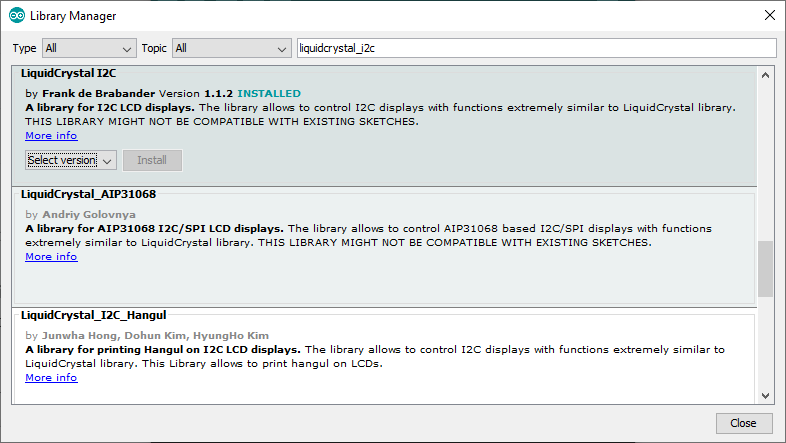 Библиотека wire для arduino для работы с шиной i2c
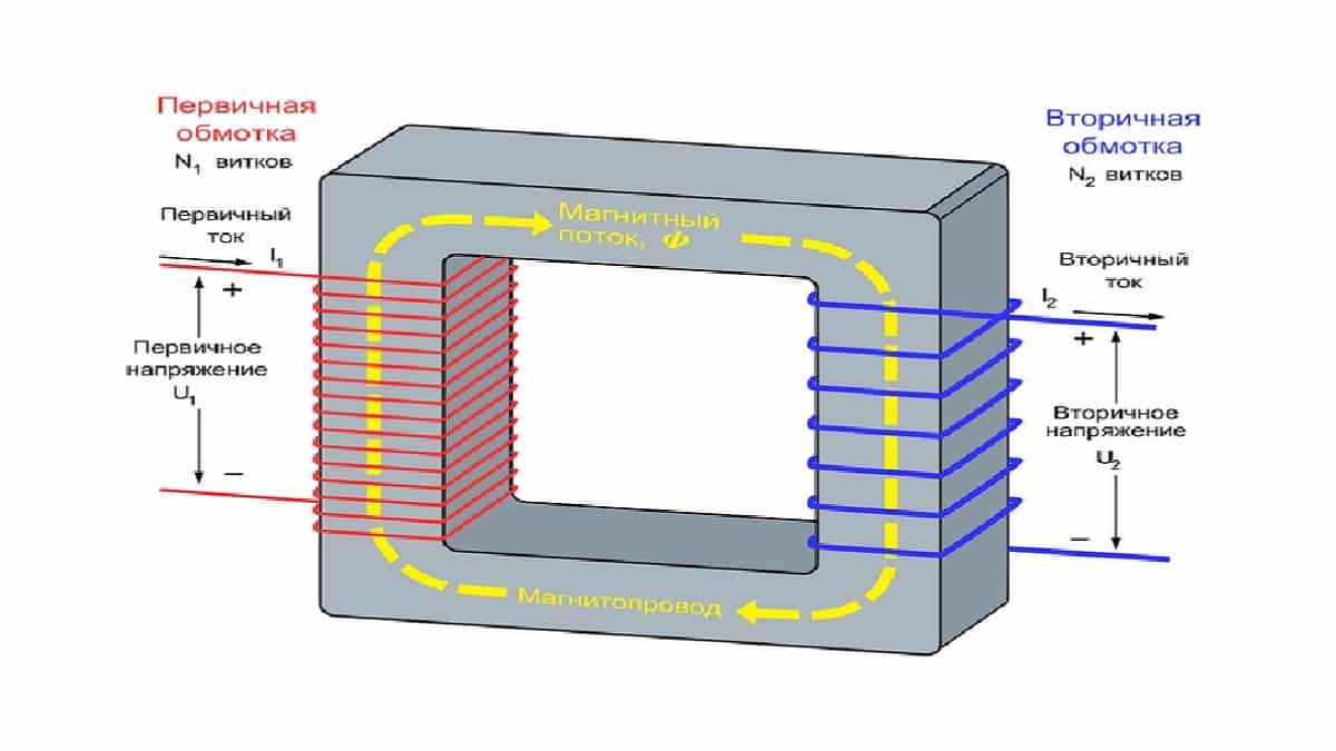 Автотрансформатр (латр): устройство, принцип действия и применение
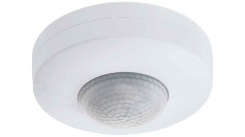 Светильники с датчиком движения для подъездов: передаем все нюансы