ESP8266 and ESP32 support
The ArduinoOTA library bundled with ESP8266 and ESP32 Arduino packages works only with native WiFi libraries. This library allows to upload a sketch to esp8266 or esp32 over Ethernet with Ethernet or EthernetENC library. Upload over the native WiFi library works too.
To use this library instead of the bundled library, the bundled library must be removed from the boards package library folder. To override the configuration of OTA upload in platform.txt, copy the platform.local.txt file from extras folder of this library next to platform.txt file in boards package installation folder. You can find the location of boards packages in Arduino IDE Preferences as the location of the preferences.txt file at the bottom of the Preferences dialog. It is clickable and opens the folder. There find the boards package in packages folder.
This library supports SPIFFS upload to esp8266 and esp32, but the IDE plugins have the network upload tool hardcoded to espota. It can’t be changed in configuration. To upload SPIFFS, call the plugin in Tools menu and after it fails to upload over network, go to location of the created bin file and upload the file with arduinoOTA tool from command line. The location of the file is printed in the IDE console window. Upload command example (linux):
(the same command can be used to upload the sketch binary, only use )
if(typeof __ez_fad_position != ‘undefined’){__ez_fad_position(‘div-gpt-ad-arduinogetstarted_com-large-mobile-banner-2-0’)};How to Make an HTTP Request
This part presents only code related to HTTP. Full code for each shield will be presents in the last part.
Declare request method, HTTP port, hostname, pathname, query string
int HTTP_PORT = 80;
String HTTP_METHOD = «GET»;
char HOST_NAME[] = «example.phpoc.com»;
String PATH_NAME = «»;
Declare a web client object
| Arduino Ethernet Shield 2 | EthernetClient client; |
| PHPoC WiFi/Ethernet Shield | PhpocClient client; |
| Arduino Uno WiFi | WiFiClient client; |
Connect to web server
if(client.connect(HOST_NAME, HTTP_PORT)) {
Serial.println(«Connected to server»);
} else {
Serial.println(«connection failed»);
}
If connected to server, send HTTP request
client.println(HTTP_METHOD + » » + PATH_NAME + » HTTP/1.1″);
client.println(«Host: » + String(HOST_NAME));
client.println(«Connection: close»);
client.println();
Read the response data from web server
while(client.available())
{
char c = client.read();
Serial.print(c);
}
if(!client.connected())
{
Serial.println(«disconnected»);
client.stop();
}
Подключение и настройка
Для начала работы с платой Uno WiFi в операционной системе Windows скачайте и установите на компьютер интегрированную среду разработки Arduino IDE.
Настройка модуля WiFi
Для первичной настройки Arduino с модулем WiFi выполните следующие действия.
Подключите питание к плате. Через несколько секунд в списке доступных сетей появится новая — с именем , где — уникальный номер платы.
Подключитесь к найденной сети и зайдите в браузере по адресу:192.168.240.1
Откроется web-интерфейс настройки платы.
Зайдите в сетевые настройки платы, нажатием на кнопку в пункте .
Выберите вашу сеть Wi-Fi из списка доступных сетей, введите пароль и подключитесь к ней.
При успешном подключении к Wi-Fi сети появится информация о присвоенном IP-адресе. Запомните или запишите его. В нашем примере мы получили адрес .Теперь на Arduino Uno WiFi можно зайти с любого устройства, подключенного к этой сети.
Для дальнейшей работы с платой переключите ваш ПК с Wi-Fi-сети на вашу домашнюю беспроводную сеть — .
Зайдите в браузере по выданному ранее IP-адресу
Откроется тот же web-интерфейс настройки платы.
Обратите внимание: в данный момент плата работает в режиме «клиент + точка доступа». Если вы хотите прошить плату по Wi-Fi, необходимо переключить режим работы платы из в
Зайдите в сетевые настройки платы, нажав на кнопку в пункте .
Переключите режим сети из в кнопкой .
В колонке отобразится режим .
Это значит, вы всё сделали верно, и можно переходить к прошивке платы по Wi-Fi.
Прошивка по WiFi
Arduino Uno WiFi имеет в своём запасе ещё один приятный бонус — возможность загружать скетчи без использования USB-кабеля в режиме OTA (Firmware Over The Air). Рассмотрим подробнее, как это сделать.
- Отключите плату от ПК и подключите к другому источнику питания — например, к блоку питания или Power Shield.
-
Запустите Arduino IDE.
-
Сообщите среде IDE, с какой платой будете работать. Для этого перейдите в меню:
Инструменты
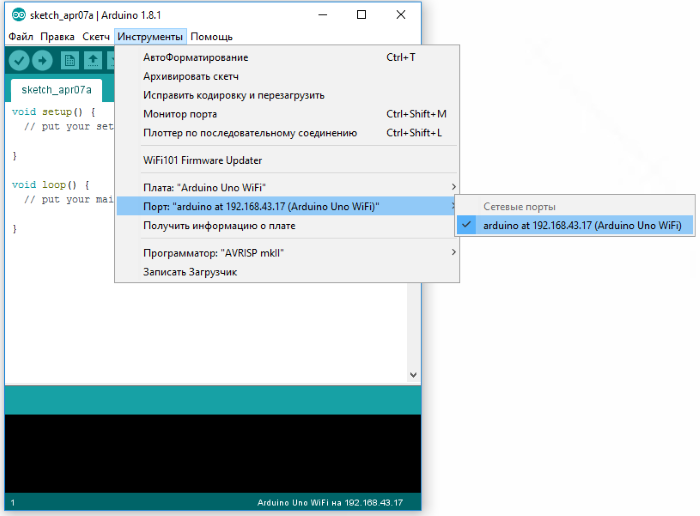
Плата и выберите плату «Arduino Uno WiFi». - Теперь необходимо сообщить среде программирования номер COM-порта, который соответствует подключённой плате.
Для этого необходимо войти в меню:
Инструменты
Порт и выбирать нужный порт.
Так как мы прошиваем Arduino по WiFi, плата определится как удалённое устройство с IP-адресом
Загрузка скетча
Среда настроена, плата подключена. Можно переходить к загрузке скетча.
Arduino IDE содержит большой список готовых примеров, в которых можно подсмотреть решение какой-либо задачи. Выберем среди примеров мигание светодиодом — скетч «Blink».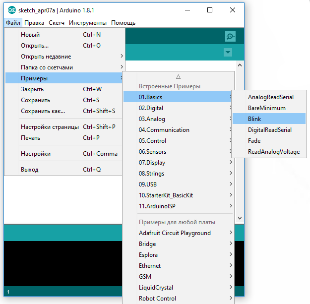
Прошейте плату, нажав на иконку загрузки программы.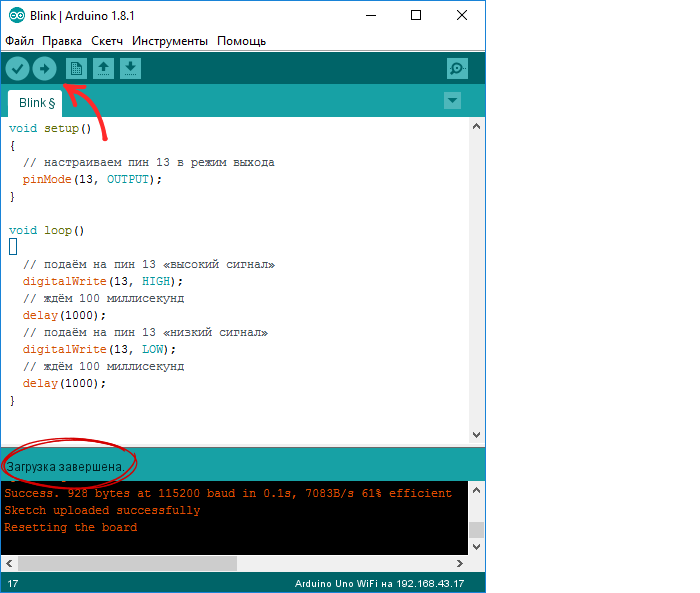
После загрузки светодиод начнёт мигать раз в секунду. Это значит, что всё получилось.
Теперь можно переходить к примерам использования.
Skeleton Arduino code for Arduino Ethernet Shield 2 when using the static IP address
Prerequisite
-
You need to get MAC address (get from the sticker)
-
You need to get an unused IP address (see )
-
You need to get the subnet mask of your network (see )
-
You need to get gateway’s IP address (see )
-
You need to get DNS server’s IP address (see )
How to program step by step
Include library
#include <SPI.h>
#include <Ethernet.h>
Declare MAC address
byte mac[] = { 0xDE, 0xAD, 0xBE, 0xEF, 0xFE, 0xED };
Declare an unused IP address, subnet mask, gateway’s IP address, and DNS server’s IP address
IPAddress ip(192, 168, 0, 5);
IPAddress gateway(192, 168, 0, 1);
IPAddress subnet(255, 255, 255, 0);
IPAddress myDns(8, 8, 8, 8);
-
Declare other objects depending on your application.
-
Start the Ethernet Shield 2
Ethernet.begin(mac, ip, myDns, gateway, subnet);
Optional, check network link status
if (Ethernet.linkStatus() == LinkON)
Serial.println(«Link status: On»);
else
Serial.println(«Link status: Off»);
※ NOTE THAT:
If you do NOT change the MAC address, it may still work. However, It may NOT work if it conflicts with the MAC address of another device in the same LAN network. In the case of losing the MAC address sticker, just use the above the MAC address for testing.
The complete skeleton code when using the static IP address
#include <SPI.h>
#include <Ethernet.h>
byte mac[] = { 0xDE, 0xAD, 0xBE, 0xEF, 0xFE, 0xED };
IPAddress ip(192, 168, 0, 5);
IPAddress gateway(192, 168, 0, 1);
IPAddress subnet(255, 255, 255, 0);
IPAddress myDns(8, 8, 8, 8);
void setup() {
Serial.begin(9600);
Ethernet.begin(mac, ip, myDns, gateway, subnet);
}
void loop() {
if (Ethernet.linkStatus() == LinkON)
Serial.println(«Link status: On»);
else
Serial.println(«Link status: Off»);
}
Upload the above code to Arduino. If succeeded, Serial Monitor shows something like below:
COM6
Send
Link status: On
Link status: On
Link status: On
Autoscroll
Show timestamp
Clear output
9600 baud
Newline
If the Serial Monitor does NOT show like above:
Basic Knowledge of Web Client and Web Server
When you access a website from your PC or smartphone, you just type the web address (URL) on a web browser, waits for a second, and then the webpage is displayed on your PC/smartphone. You do not know what your PC/smartphone does behind the screen. So, what happens behind the screen:
- Your PC/smartphone (as a web client) makes an HTTP request to a web server
- The web server returns an HTTP response to your PC/smartphone
- Your PC/smartphone receives the HTTP response and visualizes HTTP response on your screen
In this tutorial, We will make Arduino become a web client to do something similar to your PC/smartphone.
Web Address (URL)
An URL includes two parts: hostname and pathname. The hostname can be replaced by the IP address of the web server. For example: example.com/test
In HTTP GET request, URL can includes the query string. For example: example.com/test?temperature=20&humidity=70.
Query String
The query string is a set of name-value pairs, which are included in HTTP request to send data from web client to web server.
The name and value is separated by «=» character. The name-value pairs are separated by «&» character.
For example: temperature=26&humidity=70&state=2
HTTP Request
The HTTP request is composed of:
-
HTTP request header
-
(Optional) HTTP request body
HTTP request header and HTTP request body is seperated by two pair of a carriage return character (ASCII 13, or ‘\r’) and a newline character (ASCII 10, or ‘\n’).
There are many request method. Among them, there are two popular methods: GET and POST.
Модули Ethernet для Arduino
Подключить плату arduino к интернету можно несколькими способами. Беспроводное подключение прекрасно организуется с использованием платформ ESP8266 или ESP32. Можно использовать Lora модули с соответствующими WiFi-шлюзами. Но самым помехоустойчивым и “традиционным” является старый добрый Ethernet. Используя обычный RJ45 разъем и витую пару вы сможете объединить вашу плату с другим сетевым оборудованием, будь то роутер, маршрутизатор или тот же WiFi модем. Преимущества Ethernet-подключения – скорость, стабильность, бОльшая защищенность от помех. Недостатки очевидны – оборудование привязывается проводом, причем в условиях реальной эксплуатации качество этого провода должно быть высоким.
Плата расширения Arduino Ethrnet Shield
Наиболее популярные Ethernet модули для ардуино сегодня выпускаются на основе микросхемы wiznet w5100, которая способна поддерживать обмен данными с постоянной скоростью в 100 Мбит/сек. Для устройств на базе w5100 написаны готовые библиотеки, данная архитектура является простой и идеально подойдет начинающим любителям электроники, которые могут использовать как стартовую площадку для последующих проектов.
Ключевые характеристики модулей на базе W5100:
- Рабочее напряжение – 5 Вольт, подходит питание с платы Arduino.
- Внутренний буфер 16 Кб.
- Скорость соединения достигает значения в 10/100 Мбит/сек.
- Связь с платой ардуино осуществляется посредством порта SPI.
- W5100 поддерживает TCP и UDP.
Варианты модулей на базе других микросхем:
- Модуль на базе Wiznet W5500. Имеет меньшие размеры, меньше греется, имеет большую мощность.
- Модуль на базе enc28j60. Это гораздо более бюджетный вариант, дешевле W5100, но и потенциальных проблем с ним может возникнуть больше.
Arduino Library: EtherCard
This library seems a very well respected in the Arduino community and with good reason. It seems one of the most complete implementations out there.
The code below might look a little bit more complicated, but that’s mainly because of the added HTML.
CAUTION: Ethercard seems to use pin 8 instead of pin 10!
Pros:
Definitely a big plus for this library is that complex tasks like DHCP and such are easy to use, and offers easy accessible advanced features. Definitely excellent for the pro Arduino users.
Cons:
A big downside (again) is the lack of a simple to use “print” function to sent data, and I’m fully aware that me bitching about it is based on my own limited experience with working with strings and char arrays etc., but I can imagine that I’m not the only one.
Ethercard is, like UIPEthernet, not the smallest library.
Download:
EtherCard can be found at GitHub and on their project page or you can download it from Tweaking4All.
Again: I recommend getting the latest and greatest version from Github.
Download — Ethercard
| Filename: | ethercard.zip |
| Platform: | Undefined |
| Version: | |
| File size: | 116.3 kB |
| Date: | 2017-02-25 |
|
Download Now Send me a cup of Coffee |
Note: Source has been updated to accommodate the newer Arduine IDE version (line 10, added “const”).
| 12345678910111213141516171819202122232425262728293031323334353637383940414243 |
#include <EtherCard.h>// Ethernet IP, default gateway and MAC addressesstatic byte myip = { 192,168,1,200 };static byte gwip = { 192,168,1,1 };static byte mymac = { 0x74,0x69,0x69,0x2D,0x30,0x31 }; byte Ethernet::buffer500; // tcp/ip send and receive bufferconst char page PROGMEM =»HTTP/1.0 503 Service Unavailable\r\n»»Content-Type: text/html\r\n»»Retry-After: 600\r\n»»\r\n»»<html>» «<head><title>» «Hello World!» «</title></head>» «<body>» «<h3>Hello World! This is your Arduino speaking!</h3>» «</body>»»</html>»;void setup(){ Serial.begin(57600); Serial.println(«\n»); if (ether.begin(sizeof Ethernet::buffer, mymac) == ) Serial.println( «Failed to access Ethernet controller»); ether.staticSetup(myip, gwip); ether.printIp(«IP: «, ether.myip); ether.printIp(«GW: «, ether.gwip); ether.printIp(«DNS: «, ether.dnsip); }void loop(){ // wait for an incoming TCP packet, but ignore its contents if (ether.packetLoop(ether.packetReceive())) { memcpy_P(ether.tcpOffset(), page, sizeof page); ether.httpServerReply(sizeof page — 1); }} |
Краткое резюме
В этой статье мы с вами рассмотрели только небольшую часть огромного ассортимента всевозможных устройств, расширяющих функциональность ардуино. Платы расширения позволяют сосредоточиться на самом главном – логике вашей программы. Создатели шилдов предусмотрели правильный и надежный монтаж, необходимый режим питания. Все, что вам остается, это найти нужную плату, используя заветное английское слово shield, подключить ее к ардуино и загрузить скетч. Обычно любое программирование шилда заключается в выполнении простых действий по переименованию внутренних переменных уже готовой программы. В итоге мы получаем удобство в использовании и подключении, а также быстроту сборки готовых устройств или прототипов.
Минусом использования плат расширения можно назвать их стоимость и возможный потери эффективности из-за универсальности шилдов, лежащей в их природе. Для вашей узкой задачи или конечного устройства все функции шилда могут быть не нужны. В таком случае стоит использовать шилд только на этапе макетирования и тестирования, а при создании финального варианта своего устройства задуматься о замене конструкцией с собственной схемой и типом компоновки. Решать вам, все возможности для правильного выбора у вас есть.
Step 2: Shield Features
The Ethernet Shield is based upon the W51000 chip, which has an internal 16K buffer. It has a connection speed of up to 10/100Mb. This is not the fastest connection around, but is also nothing to turn your nose up at.
It relies on the Arduino Ethernet library, which comes bundled with the development environment.
There is also an on-board micro SD slot which enables you to store a heck-of-a-lot of data, and serve up entire websites using just your Arduino. This requires the use of an external SD library, which does not come bundled with the software. Using the SD card is not covered in this Instructable. However, it is covered in the Step 8 of the Wireless SD card instructable.
The board also has space for the addition of a Power over Ethernet (PoE) module, which allows you to power your Arduino over an Ethernet connection.
For a full technical overview, see the official Ethernet Shield page.
Arduino ‘network port’
The Arduino IDE detects the Arduino ‘network port’ using mDNS system. This requires the use of UDP multicast. From networking libraries supported for OTA upload only Ethernet, WiFiNina, WiFi101 and the esp libraries support multicast. For these libraries ArduinoOTA.h at defaults starts the mDNS service.
In some networks or on some computers UDP mDNS doesn’t work. You can still use the ArduinoOTA library for upload from command line or with the fake programmer trick described elsewhere in this README.
It is possible to suppress use of the mDNS service by the library. Only define NO_OTA_PORT before the include like this:
Аrduino nano распиновка
Аrduino nano распиновка — в этой статье хочу уделить немного внимания аппаратной основе плат семейства Arduino Nano. Вариации аппаратного исполнения я описал под фото.
Распиновка Arduino Nano.
Питание
Arduino Nano может быть запитан через кабель mini(micro)-USB, от внешнего источника питания с нестабилизированным напряжением 6-20 В (через вывод 30, подавать на этот вывод больше 12 В настоятельно не рекомендуется) либо со стабилизированным напряжением 5В (через вывод 27). Устройство автоматически выбирает источник питания с наибольшим напряжением.
Напряжение на микросхему FTDI FT232RL подается только в случае питания Arduino Nano через USB. Поэтому при питании устройства от других внешних источников (не USB), выход 3.3 В (формируемый микросхемой FTDI) будет неактивен, в результате чего светодиоды RX и TX могут мерцать при наличии высокого уровня сигнала на выводах 0 и 1.
Входы и выходы
Каждый из 20 (0-19, на схеме аrduino nano распиновка помещены в сиреневые параллелограммы, на той же схеме в серых параллелограммах указаны выводы микроконтроллера) цифровых выводов Arduino Nano может работать в качестве входа или выхода. Рабочее напряжение выводов — 5В. Максимальный ток, который может отдавать один вывод, составляет 40 мА, но нагружать выходы более, чем на 20 мА не рекомендуется. При этом суммарная нагрузка по всем выводам не должна превышать 200 мА. Все выводы сопряжены с внутренними подтягивающими резисторами (по умолчанию отключенными) номиналом 20-50 кОм. Помимо основных, некоторые выводы Arduino Nano могут выполнять дополнительные функции:
Последовательный интерфейс:
Последовательный интерфейс: выводы 0 (RX) и 1 (TX). Используются для получения (RX) и передачи (TX) данных по последовательному интерфейсу. Эти выводы соединены с соответствующими выводами микросхемы-преобразователя USB-UART от FTDI.
Внешние прерывания: выводы 2 и 3. Данные выводы могут быть сконфигурированы в качестве источников прерываний, возникающих при различных условиях: при низком уровне сигнала, по фронту, по спаду или при изменении сигнала. Для получения дополнительной информации см. функцию attachInterrupt().
ШИМ: выводы 3, 5, 6, 9, 10 и 11. С помощью функции analogWrite() могут выводить 8-битные аналоговые значения в виде ШИМ-сигнала.
Интерфейс SPI: выводы 10 (SS), 11 (MOSI), 12 (MISO), 13 (SCK). Данные выводы позволяют осуществлять связь по интерфейсу SPI. В устройстве реализована аппаратная поддержка SPI.
Светодиод: вывод 13. Встроенный светодиод, подсоединенный к цифровому выводу 13. При отправке значения HIGH светодиод включается, при отправке LOW — выключается.
I2С: выводы 4 (SDA) и 5 (SCL). С использованием библиотеки Wire (документация на веб-сайте Wiring) данные выводы могут осуществлять связь по интерфейсу I2C (TWI).
Помимо перечисленных на плате существует еще несколько выводов:
AREF. Опорное напряжение для аналоговых входов. Может задействоваться функцией analogReference().
Reset. Формирование низкого уровня (LOW) на этом выводе приведет к перезагрузке микроконтроллера. Обычно этот вывод служит для функционирования кнопки сброса на платах расширения.
Аналоговые входы A0-А7: входы с 10-битным аналого-цифровым преобразователем (АЦП). Напряжение поданное на аналоговый вход, обычно от 0 до 5 вольт будет преобразовано в значение от 0 до 1023, это 1024 шага с разрешением 0.0049 Вольт. Источник опорного напряжения может быть изменен.
Среда программирования Arduino IDE поддерживает работу не со всеми устройствами, входящими в состав микроконтроллера. Например, остался без внимания аналоговый компаратор. Пользоваться им можно, но придется напрямую обращаться к регистрам.
Схема соединений разъёмов J1 и J2.
Схема соединений микроконтроллера. В качестве МК могут быть применены ATMega 328P или ATMega 168P.
Схема соединений преобразователя USB-UART.
Есть версии плат с микросхемами CH340G(более капризные), в оригинальной версии стоит FT232RL. В базовой версии устанавливается разъём mini-USB, но попадаются версии и с более удобным разъёмом micro-USB.
Соединения цепей питания и разъёма ICSP. Есть версии плат с номинальным напряжением питания 5 В или 3,3 В.
Предыдущая запись Активная концертная акустика
Следующая запись Прибой Э014С
REQUIREMENTS for ARDUINO ETHERNET SHIELD
We have to plug this shield on our Arduino board but below are some mandatory requirements:
- RJ45 cable for connection to network
- Arduino board (for sure. Because this shield cannot be used as standalone project)
- Operating voltage of 5 V should be provided by Arduino board
- Make connection with Arduino board on SPI port
- Power over Ethernet module required (this module is designed for power extraction from conventional twisted pair Ethernet cable) which should meet following requirements:
- Low output noise and ripple
- Input voltage: 36 V – 57 V
- Over-load protection
- Output voltage: 9V
- The input to output isolation should be of 1500 V
- Highly efficient DC/DC converter
- 3af compliant
One important thing that is to be noted here is that both SD card and W5100 share SPI bus as Arduino communicates via SPI port so we can use only one of them. If we want to use both of them then we have to check their corresponding library.
Программа
Смысл проекта такой же как и с bluetooth. Плата должна получить от нас сигнал и установить реле в нужное состояние. Тогда подключенное к реле оборудование включится или выключится соответственно.
Используем пример из библиотеки Ethernet.
Откроем скетч из Меню File -> Examples -> Ethernet -> WebServer
Здесь используются библиотеки <SPI.h> и <Ethernet.h>
Вы можете задать mac адрес и ip адрес для вашей платы. Ip адрес должен подходить для вашей локальной сети. HTTP сервер будет работать на 80 порту как обычно. А реле подключим к 7 пину.
В функции setup() настраиваем все необходимые функции для работы через интернет. И раскомментируем строку Ethernet.init(10);
Настроим пин для реле на вывод и выключим его.
Теперь разберемся с циклом loop(). Каждый раз, когда к серверу подключается новый клиент, мы должны передать ему веб страницу с необходимой информацией. Используем монитор последовательного порта для отладки программы. Информацию от клиента мы будем получать через http заголовки и для этого считаем всю информацию, которую мы можем получить при соединении к серверу.
Таким образом мы получили строку, в которой будет вся имеющаяся информация. В том числе о хосте, рефферере и данных о браузере. Из-за того, что данные в рефферере и хосте будут дублироваться, а нам нужна только строка хоста, уберем лишнюю информацию.
Теперь мы можемиспользовать информацию о состоянии реле и сформировать нужную веб страницу для пользователя.
В итоге получим кнопку со ссылкой на включение реле, если реле выключено. И наоборот, на выключение, если свет включен в настоящий момент.
Understanding the Code
Basic Code Structure
The code consists of an Arduino sketch that is loaded to the Arduino MEGA and an index.htm file that is copied to the micro SD card. The index.htm page contains HTML, CSS and JavaScript. The micro SD card is inserted into the micro SD card socket on the Ethernet shield.
The Arduino MEGA and Ethernet shield are programmed to behave as a web server that serves up the web page from the micro SD card when a web browser connects to the server and requests the page.
The JavaScript that is embedded in the page communicates with the Arduino web server using Ajax after the web page has been loaded to the web browser.
Prerequisites for Understanding the Code
The code for this tutorial is listed and explained below, but a basic understanding of the technologies used in this tutorial will be needed. All the basics of how an Arduino web server, web pages and Ajax work are explained in the Arduino Ethernet web server tutorial on this website.
How the Code Design was Started
The code in this tutorial is based on part 16 of the web server tutorial – SD card web server I/O but is modified to use only outputs for the 24 outputs.
It would be a lot of work and also the HTML file would be bigger if this project accessed the outputs directly using unique names like the project that it is based on does. Because of this, the other major change to the base code was to make use of loops to access the 24 outputs sequentially in the Arduino code and JavaScript.
How the LED is Controlled
Web Page and HTML
Web Page and HTML Code with Checkbox Unchecked
The Arduino web server serves up a page that allows the user to click a check box to switch the LED on and off. The web page is shown here:
LED Web Server Web Page — Checkbox Unchecked
The HTML code that the Arduino web server sends to the web browser is shown below.
LED Web Server Web Page HTML Code — Checkbox Unchecked
Web Page and HTML Code with Checkbox Checked
After clicking the checkbox to switch the LED on, the web page and HTML code now look as follows:
LED Web Page with Checkbox Checked
Take note in the above image that the web browser added /?LED2=2 to the end of the URL field after the checkbox was clicked.
LED Web Page HTML Code with Checkbox Checked
In the above image, the Arduino changed the HTML page that it sent to the browser so that the checkbox will be shown with a check mark in it. The change to the code is highlighted in the image and it can be seen that checked was added.
New HTML Tags
Two new HTML tags are introduced in the above HTML code, namely <form> and <input>.
HTML <form> Tag
A form tag contains form controls, such as the checkbox used in this example. In this form, method=»get» in the opening form tag will result in the form being submitted using an HTTP GET request. This also results in the /?LED2=2 text being added in the URL field of the web browser.
HTML <input> Tag
A single control is added to the HTML form using the <input> tag. The input tag does not have a corresponding closing tag.
In this example, the input tag is used to create a checkbox. The following fields are included in the input tag:
- type=»checkbox» – displays this input control as a checkbox
- name=»LED2″ – user defined name of the control
- value=»2″ – user defined value of the control
- onclick=»submit();» – submit the form when the checkbox control is clicked
- checked – when present the checkbox is checked, otherwise it is blank
HTTP Request and Response
When the checkbox is clicked, it will generate an HTTP GET request that sends the name and value from the checkbox to the Arduino server.
The following is an example of an HTTP request sent from the Firefox browser to the Arduino server after clicking the checkbox:
GET /?LED2=2 HTTP/1.1
Host: 10.0.0.20
User-Agent: Mozilla/5.0 (X11; Ubuntu; Linux i686; rv:18.0) Gecko/20100101 Firefox/18.0
Accept: text/html,application/xhtml+xml,application/xml;q=0.9,*/*;q=0.8
Accept-Language: en-ZA,en-GB;q=0.8,en-US;q=0.5,en;q=0.3
Accept-Encoding: gzip, deflate
Referer: http://10.0.0.20/
Connection: keep-alive
When unchecking the checkbox, the following HTTP request is sent from the browser to the Arduino web server:
GET / HTTP/1.1
Host: 10.0.0.20
User-Agent: Mozilla/5.0 (X11; Ubuntu; Linux i686; rv:18.0) Gecko/20100101 Firefox/18.0
Accept: text/html,application/xhtml+xml,application/xml;q=0.9,*/*;q=0.8
Accept-Language: en-ZA,en-GB;q=0.8,en-US;q=0.5,en;q=0.3
Accept-Encoding: gzip, deflate
Referer: http://10.0.0.20/?LED2=2
Connection: keep-alive
The Arduino sketch in this example reads the HTTP request header and checks for the text LED2=2 and if found, the Arduino will toggle the LED from off to on or on to off.
Both of the above requests contain the LED2=2 text although in different places. When checking the box, the text is part of the GET request line. When unchecking the box, the text is part of the Referer: header.
With this background information, we can now see how the Arduino sketch works.
Books that may interest you:
Step 5: Client
You can also use the Ethernet Shield as a client. In other words, you can use it to read websites like a web browser.
Websites have a lot of text both visible and hidden, which makes programming on the client side very tricky. Reading information from websites typically involves parsing a lot of strings. This is maddening, but worth it, if that is what you intend to do.
I was going to write some code to read Twitter messages, but such a code already exists as an example within the Arduino programmer. Instead, I simply modified it slightly to turn on an LED if a special message is read.
To make this work connect the positive lead an LED to pin D2, and the negative lead in series with a 220 ohm resistor to ground.
Don’t forget to enter your own IP address into the code below, or it will not work.
Here is the code:
<pre>/*
  Twitter Client with Strings

 This sketch connects to Twitter using an Ethernet shield. It parses the XML
 returned, and looks for <text>this is a tweet</text>

 You can use the Arduino Ethernet shield, or the Adafruit Ethernet shield,
 either one will work, as long as it's got a Wiznet Ethernet module on board.

 This example uses the DHCP routines in the Ethernet library which is part of the
 Arduino core from version 1.0 beta 1

 This example uses the String library, which is part of the Arduino core from
 version 0019.

 Circuit:
  * Ethernet shield attached to pins 10, 11, 12, 13

 created 21 May 2011
 by Tom Igoe

 This code is in the public domain.

 */
#include <SPI.h>
#include <Ethernet.h>


// Enter a MAC address and IP address for your controller below.
// The IP address will be dependent on your local network:
byte mac[] = {
  0x00, 0xAA, 0xBB, 0xCC, 0xDE, 0x01 };
IPAddress ip(191,11,1,1); //<<< ENTER YOUR IP ADDRESS HERE!!!

// initialize the library instance:
EthernetClient client;

const int requestInterval = 60000;  // delay between requests

char serverName[] = "api.twitter.com";  // twitter URL

boolean requested;                   // whether you've made a request since connecting
long lastAttemptTime = 0;            // last time you connected to the server, in milliseconds

String currentLine = "";            // string to hold the text from server
String tweet = "";                  // string to hold the tweet
boolean readingTweet = false;       // if you're currently reading the tweet

void setup() {

  pinMode(2, OUTPUT);

  // reserve space for the strings:
  currentLine.reserve(256);
  tweet.reserve(150);

// initialize serial:
  Serial.begin(9600);
  // attempt a DHCP connection:
  if (!Ethernet.begin(mac)) {
    // if DHCP fails, start with a hard-coded address:
    Ethernet.begin(mac, ip);
  }
  // connect to Twitter:
  connectToServer();
}


void loop()
{
  if (client.connected()) {
    if (client.available()) {
      // read incoming bytes:
      char inChar = client.read();

      // add incoming byte to end of line:
      currentLine += inChar;

      // if you get a newline, clear the line:
      if (inChar == '\n') {
        currentLine = "";
      }
      // if the current line ends with <text>, it will
      // be followed by the tweet:
      if ( currentLine.endsWith("<text>")) {
        // tweet is beginning. Clear the tweet string:
        readingTweet = true;
        tweet = "";
      }
      // if you're currently reading the bytes of a tweet,
      // add them to the tweet String:
      if (readingTweet) {
        if (inChar != '<') {
          tweet += inChar;
        }
        else {
          // if you got a "<" character,
          // you've reached the end of the tweet:
          readingTweet = false;
          Serial.println(tweet);

          if(tweet == ">Hello Cruel World"){
           digitalWrite(2, HIGH);
           Serial.println("LED ON!");
          }
          if(tweet != ">Hello Cruel World"){
           digitalWrite(2, LOW);
           Serial.println("LED OFF!");
          }

          // close the connection to the server:
          client.stop();
        }
      }
    }
  }
  else if (millis() - lastAttemptTime > requestInterval) {
    // if you're not connected, and two minutes have passed since
    // your last connection, then attempt to connect again:
    connectToServer();
  }
}

void connectToServer() {
  // attempt to connect, and wait a millisecond:
  Serial.println("connecting to server...");
  if (client.connect(serverName, 80)) {
    Serial.println("making HTTP request...");
  // make HTTP GET request to twitter:
    client.println("GET /1/statuses/user_timeline.xml?screen_name=RandyMcTester&count=1 HTTP/1.1");
    client.println("HOST: api.twitter.com");
    client.println();
  }
  // note the time of this connect attempt:
  lastAttemptTime = millis();
}
Presumably you are going to want to read something other than the recent post on the RandyMcTester Twitter feed.
To read other Twitter feeds, change the following bit of text:
client.println(«GET /1/statuses/user_timeline.xml?screen_name=&count=1 HTTP/1.1»);
Подключение Arduino Nano
Подключение платы Arduino Nano к компьютеру не представляет особого труда – оно аналогично обычной плате Uno. Единственная сложность может возникнуть при работе с платой на базе чипа ATMEGA 168 – в настройках нужно выбрать сперва плату Nano, а затем нужный вариант процессора.
Установка драйвера для CH340
Микросхема CH340 часто используется в платах Ардуино со встроенным USB-to-Serial преобразователем. Она позволяет уменьшить затраты на производство плат, не влияя на ее работоспособность. При помощи этого программатора можно легко прошивать платы Ардуино. Для того, чтобы начать работать с этой микросхемой, нужно установить драйвер на компьютер.
Установка выполняется в несколько этапов:
Настройка Arduino IDE
Стандартная среда разработки Arduino IDE используется для работы всех видов Ардуино с компьютером. Чтобы начать работу, нужно сначала скачать Arduino IDE с официального сайта и установить ее. Удобнее скачивать Windows Installer, особенно если среда разработки будет установлена на постоянном рабочем компьютере. Если скачан архив, то его нужно распаковать и запустить файл Arduino.exe.
Как только среда установлена, нужно ее запустить. Для этого нужно подключить к компьютеру саму плату Ардуино через USB. Затем перейти в меню Пуск >> Панель управления >> Диспетчер устройств, найти там Порты COM и LPT. В списке появится установленная плата и указан номер порта, к которому подключается плата.
После этого нужно запустить Arduino IDE, перейти в меню Инструменты >> Порт, и указать порт, к которому присоединена Ардуино. В меня Инструменты>> Платы нужно выбрать модель подключенной платы, в данном случае Arduino Nano. Если у вас плата Nano версии 2.0, то вам нужно также выбрать вариант процессора в соответствующем меню.
Важно помнить, что если к компьютеру будет подключаться другая плата, настройки снова нужно будет поменять на соответствующее устройство
Hardware and Circuit Diagram
An Arduino MEGA 2560 and Arduino Ethernet shield are used in this project. A 2GB micro SD card is used to store the web page that is hosted by the Arduino.
The circuit diagram shows how the LEDs are connected to the Arduino. Only the first two and last two LEDs with series resistors are shown in the circuit as the rest of the LEDs are connected in the same way sequentially from pin 26 to pin 49 of the Arduino MEGA.
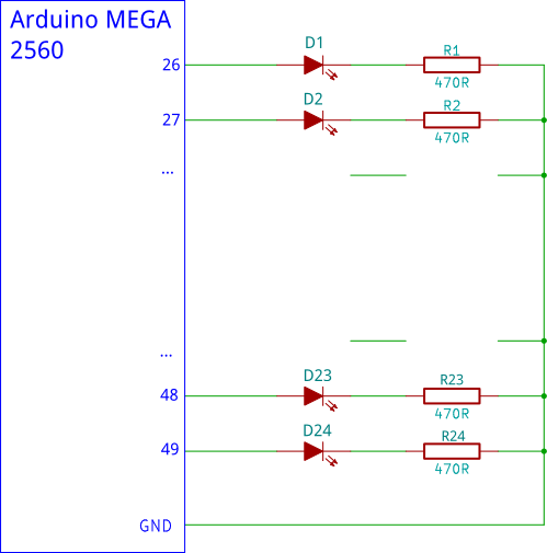
Arduino MEGA LED Connection Circuit Diagram
NOTE: Pins 50 to 53 (four pins) can not be used as outputs when using the Ethernet shield. This is because these are SPI port pins that are used to control the Ethernet chip and SD card.
Update and Correction 3 June 2015: In the original article, pin 53 was said to be the SS (Slave Select – of the SPI port) that controls the Ethernet chip (W5100). Although pin 53 on the MEGA is a SS pin from the SPI port, it is not the same SS used by the Ethernet shield.
To summarise: only pins 50 to 52 connect to the Ethernet shield through the ICSP header for SPI data and clock purposes – pin 53 is actually available. Pin 53 on the MEGA is called SS and pin 10 on the Ethernet shield is called SS but they are not connected.
Further to the above, the Arduino Ethernet shield web page has the following to say:
Arduino communicates with both the W5100 and SD card using the SPI bus (through the ICSP header). This is on digital pins 10, 11, 12, and 13 on the Uno and pins 50, 51, and 52 on the Mega. On both boards, pin 10 is used to select the W5100 and pin 4 for the SD card. These pins cannot be used for general I/O. On the Mega, the hardware SS pin, 53, is not used to select either the W5100 or the SD card, but it must be kept as an output or the SPI interface won’t work.
Books that may interest you:
Похожие записи:
 Работа по перемещению заряда в электрическом поле
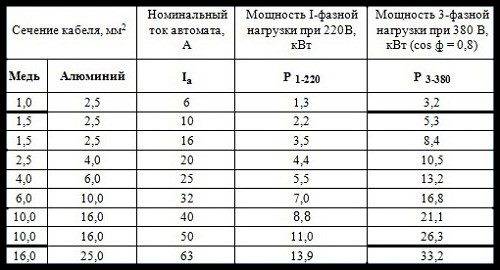 Таблица потребления электроэнергии бытовыми приборами
Пуэ-7 п.1.3.10-1.3.9 допустимые длительные токи для проводов, шнуров и кабелей с резиновой или пластмассовой изоляцией
Таблица потребления электроэнергии бытовыми приборами
Пуэ-7 п.1.3.10-1.3.9 допустимые длительные токи для проводов, шнуров и кабелей с резиновой или пластмассовой изоляцией
 Как установить электрический полотенцесушитель?
 Закон кулона, конденсатор, сила тока, закон ома, закон джоуля
Применение микросхем крен
Закон кулона, конденсатор, сила тока, закон ома, закон джоуля
Применение микросхем крен