Что такое Arduino Mega Server?
Это операционная система для вашего контроллера
Удобный веб-интерфейс, файлы без ограничений, поддержка современных технологий, работа через проводной и беспроводной интерфейсы, адаптивный дизайн и т. д.
Кроссплатформенная система Работает на Arduino Mega, Due, 101, M0, ESP8266, ESP32 и т. д.
Основа для ваших DIY проектов Основа вашего умного дома, управления различным оборудованием и т. д.
Обучающая платформа Для школ и развивающих центров для освоения программирования, электроники, дизайна, проектирования и т. п.
AMS это: дистрибутивы для 10+ платформ, 24 000+ загрузок, 15+ компаний-партнёров, 600 000+ просмотров статей на Хабре, десятки реализованных проектов и многое, многое другое
Bluetooth Controller 8 Lamp
Платформа Arduino была создана в 2003 году. Всеобщего внимания она достигла, благодаря низкой цене, а также многомилионному сообществу, направленного на углубленное изучение программирования. Микропроцессоры и микроконтроллеры поставляются с платами. Самыми популярными считаются Arduino. Итальянские модели имеет много функций по расширению и исследованию встроенных Pro систем.
Bluetooth Controller 8 Lamp создан для регулировки функций Ардуино 8 канальным контроллером. Работает при помощи модулей Bluetooth HC-05, HC-06 и HC-07. 8 кнопочный интерфейс соответствует каждой лампочке.
Метод активен только в пределах видимости. В сравнении с другими беспроводными способами — этот самый дешевый. Комплектующие платы стоят менее 1 доллара. Для работы подходят даже подержанные варианты. Статичные девайсы, используя инфракрасный контроллер в потолочных светодиодных лентах, решают легко проблемы, возникшие в процессе.
Веб-сервер — ваша первая сетевая программа Arduino +6
- 27.09.17 13:58
•
Scorobey
•
#338844
•
Хабрахабр
•
Tutorial
•
•
4600
Разработка под Windows, Python, Промышленное программирование

Постановка задачи
- Использовать библиотеку Arduino Ethernet с расширением Arduino Ethernet Shield для создания веб-сервера.
- Создать удаленный доступ к Arduino с использованием сети вашего домашнего компьютера.
- Использовать стандартный пример Arduino для обеспечения значений влажности и датчика движения с помощью веб-сервера.
- Разработать веб-приложений с использованием Python.
Этапы решения поставленной задачи
- Проектирование и создание аппаратных средств для использования Arduino и Ethernet Shield.
- Запуск примера по умолчанию из среды разработки Arduino как начальную точку создания сервера.
- Изменение примера для размещения вашего оборудования и повторного развертывания кода.
- Разработка веб-приложений с использованием Python.
Arduino Uno
80EthernetServer
setup ()Ethernet.being ()macipserver.begin ()
loop ()clientEthernetClient
WebServer_Custom.inoExercise 1 — Web Serverclient.print ()(данные о данных)поддерживает очень ограниченное количество подключений
Первое веб-приложение Python
web.pyweb.pyGETweb.pyGETweb.py
0.0.0.00.0.0.0127.0.0.1localhostGETGETHello, world!web.pyurlsweb.application ()web.pyweb.pyapplication(urls, global())web.py8080web.py8888
web.pyGETweb.py
web.pyweb.pyurls
web.pyweb.py
POST
template.render ()
test.htmltemplates
$def with ()formi$: form.render ()
render.test ()test ()
TextboxButtonForm
TextboxPasswordDropboxRadiotoCheckbox
Ссылки
- Прототипирование в среде Python-Arduino.
- Методы разработки потока программного обеспечения датчиков движения, работающих с Arduino.
- Использование Python для обработки в реальном масштабе времени информации от датчиков, работающих с Arduino.
- Subnetwork.
- web.py templating system.
Комментарии (2):
-
AotD
28.09.17 06:07/#10441464
1. Зачем использовать пример получения IP по DHCP если потом мы прибиваем IP гвоздями?
2. Как вообще связаны части статьи про Arduino и Python? Кроме того что и там и там есть веб-сервер. -
iig
28.09.17 03:57/#10442570
/ -1Да, как-то слишком много и запутано.
Постановка задачи
Использовать библиотеку Arduino Ethernet с расширением Arduino Ethernet Shield для создания веб-сервера.В статье доказано, и я согласен с автором, что так делать нельзя.
Создать удаленный доступ к Arduino с использованием сети вашего домашнего компьютера.
Лучше делать наоборот. На ардуине — клиент (mqtt, зачем строить велосипед), сервер — можно взять готовый.
Использовать стандартный пример Arduino для обеспечения значений влажности и датчика движения с помощью веб-сервера.
Будет лишний аргумент антиардуинщикам: «ха, на ихней ардуине только так и делают».
Разработать веб-приложений с использованием Python.
Python так Python… Но каким боком к нему ваш датчик на ардуине?
How the LED is Controlled
Web Page and HTML
Web Page and HTML Code with Checkbox Unchecked
The Arduino web server serves up a page that allows the user to click a check box to switch the LED on and off. The web page is shown here:
LED Web Server Web Page — Checkbox Unchecked
The HTML code that the Arduino web server sends to the web browser is shown below.
LED Web Server Web Page HTML Code — Checkbox Unchecked
Web Page and HTML Code with Checkbox Checked
After clicking the checkbox to switch the LED on, the web page and HTML code now look as follows:
LED Web Page with Checkbox Checked
Take note in the above image that the web browser added /?LED2=2 to the end of the URL field after the checkbox was clicked.
LED Web Page HTML Code with Checkbox Checked
In the above image, the Arduino changed the HTML page that it sent to the browser so that the checkbox will be shown with a check mark in it. The change to the code is highlighted in the image and it can be seen that checked was added.
New HTML Tags
Two new HTML tags are introduced in the above HTML code, namely <form> and <input>.
HTML <form> Tag
A form tag contains form controls, such as the checkbox used in this example. In this form, method=»get» in the opening form tag will result in the form being submitted using an HTTP GET request. This also results in the /?LED2=2 text being added in the URL field of the web browser.
HTML <input> Tag
A single control is added to the HTML form using the <input> tag. The input tag does not have a corresponding closing tag.
In this example, the input tag is used to create a checkbox. The following fields are included in the input tag:
- type=»checkbox» – displays this input control as a checkbox
- name=»LED2″ – user defined name of the control
- value=»2″ – user defined value of the control
- onclick=»submit();» – submit the form when the checkbox control is clicked
- checked – when present the checkbox is checked, otherwise it is blank
HTTP Request and Response
When the checkbox is clicked, it will generate an HTTP GET request that sends the name and value from the checkbox to the Arduino server.
The following is an example of an HTTP request sent from the Firefox browser to the Arduino server after clicking the checkbox:
GET /?LED2=2 HTTP/1.1
Host: 10.0.0.20
User-Agent: Mozilla/5.0 (X11; Ubuntu; Linux i686; rv:18.0) Gecko/20100101 Firefox/18.0
Accept: text/html,application/xhtml+xml,application/xml;q=0.9,*/*;q=0.8
Accept-Language: en-ZA,en-GB;q=0.8,en-US;q=0.5,en;q=0.3
Accept-Encoding: gzip, deflate
Referer: http://10.0.0.20/
Connection: keep-alive
When unchecking the checkbox, the following HTTP request is sent from the browser to the Arduino web server:
GET / HTTP/1.1
Host: 10.0.0.20
User-Agent: Mozilla/5.0 (X11; Ubuntu; Linux i686; rv:18.0) Gecko/20100101 Firefox/18.0
Accept: text/html,application/xhtml+xml,application/xml;q=0.9,*/*;q=0.8
Accept-Language: en-ZA,en-GB;q=0.8,en-US;q=0.5,en;q=0.3
Accept-Encoding: gzip, deflate
Referer: http://10.0.0.20/?LED2=2
Connection: keep-alive
The Arduino sketch in this example reads the HTTP request header and checks for the text LED2=2 and if found, the Arduino will toggle the LED from off to on or on to off.
Both of the above requests contain the LED2=2 text although in different places. When checking the box, the text is part of the GET request line. When unchecking the box, the text is part of the Referer: header.
With this background information, we can now see how the Arduino sketch works.
Books that may interest you:
PROJECT WORKING:
Arduino web server can be accessed by the devices within that LAN to control the LED’s or other components. ESP8266 will remember the AP’s that it has been connected to previously. It will get connected to AP as soon as hotspot in your device is turned ON. Once connected, a LAN will be created. Once Arduino detects a connection via ESP8266, it will start sending commands to ESP module to create a server. I have added a LED to indicate server creation. Mostly it will take about two seconds from the moment ESP is connected to WiFi AP.
Once the Arduino web server is ready, open any browser in the devices connected to the LAN and access the IP address assigned to ESP8266 module. Arduino will send a piece of HTML code to the client via ESP module and a webpage will be displayed on your device browser. HTML codes from the Arduino were built to display button in the webpage. Using these buttons user can feed input back to Arduino. Based on the received inputs, Arduino will activate/deactivate LED’s or any other devices that are connected to it.
TESTING YOUR ESP8266:
I strongly recommend this step since ESP8266 can be buggy and it’s quite necessary to have this tested. Upload the bare minimum code to the Arduino and connect the ESP8266 as shown in the schematic. Once done use the following commands, but remember to select “Both NL & CR” & Baud rate as 56700 which is default baud rate used by ESP module.
AT – OK
AT+RST
AT+CWMODE=3
AT+CWJAP=”SSID”,”Password”
The above command will make your ESP8266 to join the network you wish and it will remember the AP even after powered down. This is important in terms of this project because the code is developed in an assumption that ESP8266 was already connected to AP or hot spot of mobile device which we will use. This is because connecting to AP through the code seems to make things complex with no considerable benefits to this project.
AT+CIOBAUD=9600
This command is to alter the baud rate at which the ESP module operate. I had to do this since ESP modules worked better with this baud rate than higher speed.
Arduino Uno Program
#include "DHT.h"
#include <SPI.h>
#include <Ethernet.h>
#define DHTPIN 8
#define DHTTYPE DHT22

DHT sensor(DHTPIN, DHTTYPE);
byte mac[] = {
               0xDE, 0xAD, 0xBE, 0xEF, 0xFE, 0xED
             };

IPAddress ip(192, 168, 1, 177);
EthernetServer server(80);

void setup()
{
  Serial.begin (9600);
  sensor.begin( );
  Ethernet.begin(mac, ip);
  server.begin( );
  Serial.print("Your IP Adress is ");
  Serial.println(Ethernet.localIP( ) );
}

void loop( )
{
  float humidity = sensor.readHumidity( );
  float temperature_C = sensor.readTemperature( );
  float temperature_F = sensor.readTemperature (true);
  if (isnan(humidity) || isnan(temperature_C) || isnan(temperature_F))
  {
    Serial.println("Failed to read from DHT sensor!");
    return;
  }
  float heat_indexF = sensor.computeHeatIndex(temperature_F, humidity);
  float heat_indexC = sensor.convertFtoC(heat_indexF);

  EthernetClient webpage = server.available();
  if (webpage)
    {
      Serial.println("new webpage");
      boolean currentLineIsBlank = true;
      while (webpage.connected ( ) )
        {
          if (webpage.available ( ) )
            {
              char character = webpage.read ( );
              Serial.write(character);
              if (character == '\n' && currentLineIsBlank)
                {
                  webpage.println ("HTTP/1.1 200 OK");
                  webpage.println ("Content-Type: text/html");
                  webpage.println ("Connection: close");
                  webpage.println ("Refresh: 5");
                  webpage.println ( );
                  webpage.println ("<!DOCTYPE HTML>");
                  webpage.println ("<html>");
                  webpage.print ("<Title>Arduino Ethernet Webserver </Title>");
                  webpage.print ("<h1>Arduino Ethernet Shield Webserver </h1>");
                  webpage.print ("<h3><a href='http://electrosome.com'>Visit us for Amazing
                                  Projects</a> </h3>");
                  webpage.print ("<h4>Temperature in C: ");
                  webpage.print (temperature_C);
                  webpage.print ("</h4><h4>Temperature in Fah: ");
                  webpage.print (temperature_F);
                  webpage.print ("</h4><h4>Humidity: ");
                  webpage.print (humidity);
                  webpage.print ("</h4><h4>Heat Index in F: ");
                  webpage.println (heat_indexF);
                  webpage.println ("</h4><h4>Heat Index in C: ");
                  webpage.println (heat_indexC);
                  webpage.println ("<br />");
                  webpage.println ("</html>");
                  break;
                }

                if ( character == '\n')
                  {
                    currentLineIsBlank = true;
                  }
                else if (character != '\r')
                  {
                    currentLineIsBlank = false;
            }
        }
    }
    delay(1);
    webpage.stop();
    Serial.println("webpage disconnected");
  }
}
References
Arduino (arduino.cc)
Arduino web server example WebServer. Code can be found in the Arduino IDE under File → Examples → Ethernet → WebServer
Arduino Ethernet Library Reference.
Arduino SD Library Reference and examples from the IDE found under File → Examples → SD
Starting Electronics
Arduino Ethernet shield web server tutorial – explains web and web server technology in a series of tutorials.
Programming and using an Arduino Ethernet board – an Arduino Ethernet board is like an Arduino Uno, but has built in Ethernet and no USB port.
Connecting and testing an Arduino Ethernet shield – how to test an Arduino Ethernet shield or other Arduino Ethernet enabled board.
Testing an Arduino Ethernet shield SD card – testing the SD card socket on an Arduino Ethernet shield or other Arduino board that has an SD card.
Arduino User Contributed Code and Discussion
WebServerST – web server by SurferTim.
More information and discussion at the Arduino forum.
Books that may interest you:
Arduino Mega Server
Да, это снова Ардуино, но не спешите закрывать страничку, на этот раз вас ждёт нечто действительно новое и интересное. В основном в этой статье речь пойдёт о микроконтроллерных платах Arduino Mega и плате сетевого интерфейса Ethernet Shield W5100 и о том чуде, которое можно с ними сотворить если позволить себе выйти за рамки стереотипов.
Итак, что собой представляет типовая плата Arduino? «Убогий» 8-битный микроконтроллер со смешным объёмом оперативной памяти (в случае Меги это 8 килобайт) и таким же смешным объёмом флеш-памяти (256 килобайт для Меги). Некую живость пейзажу добавляют платы расширения, в нашем случае это Ethernet Shield, но принципиально это ничего не меняет. Область применения подобных плат это маргинальные поделки и знаменитое моргание светодиодами.
Но так было до последнего момента. Теперь в природе существует Arduino Mega Server, который принципиально меняет положение вещей. Например, что бы вы сказали, если бы столкнулись с утверждением, что:
- на Arduino можно организовать полноценный веб-сервер, не имеющий ограничений на размер и количество файлов?
- динамически обновляющий контент без остановки сервера?
- поддерживающий в полном объёме HTML5, CSS3, JavaScript, Ajax, Processig, THREE.js, сторонние библиотеки и т. д.?
- Позволяющий «хостить» на микроконтроллере сотни полноценных сайтов (с известными ограничениями)?
- Позволяющий держать у себя в кладовке на одном из контроллеров умного дома, например, полную работающую копию Хабра и ещё десятка подобных сайтов (в пределах 32 гигабайт)?
Вы бы сказали, что это попросту невозможно.
Однако это факт. И вы можете скачать дистрибутив к себе на компьютер и убедиться в этом сами (кроме Хабра, это гипотетический пример).
В чём же секрет? Всё очень просто. Плата сетевого интерфейса поддерживает подключение SD карт памяти объёмом до 32 гигабайт и ничто не мешает нам задействовать её для хранения файлов веб-сервера и собственно контента. Нужно просто решить задачу интеграции всего этого богатства в одну систему.
Чтобы всё это заработало нужно написать серверный движок для Ардуино и научить его выдавать содержимое флеш-карты памяти по запросам браузеров. Собственно, почти всё. Нужно ещё каким-то образом организовать обновление файлов сервера и контента «на лету», для того, чтобы вам не приходилось вставать с дивана, отключать питание Ардуино и вынимать карту памяти каждый раз, когда нужно изменить что-либо в конфигурации сервера или поменять что-либо в контенте. Эта тяжёлая, но благородная миссия возложена на Arduino Serial Commander, который управляет загрузкой файлов на работающий сервер, без остановки оного.
Если всё так просто, то почему это не было сделано раньше? Вот это действительно вопрос. Моя версия — стереотипность мышления. Вам же сказали, что это 8-битный контроллер, какой ещё THREE.js? Какой хостинг? О чём вы вообще говорите? Справедливости ради нужно сказать, что все части пазла уже существовали в природе, но существовали они в совершенно непотребном виде — либо в виде абстрактного сервера, полностью оторванного от реальности, либо в виде Ajax примеров, но опять же только с двумя абстрактными кнопками, с которыми непонятно, что вообще нужно делать.
Step 6: Storage Options
This is a more in depth view of the storage options I explained in the previous step.
Ram:
The first option is to store the site in the Arduino’s ram. This is the simplest way because you simply call the client.print() function and write your html code inside it. It is limited to about 1500 characters, because the Arduino only has 2048 bytes of ram.*
Ex: client.print(«<html>…</html>»);
Program Memory:
Wouldn’t it be great if you could store the code in the program memory instead of the ram. Well, actually, the above option does that, but the compiler then makes the micro read all of that out into the ram upon start up. How do we fix that? We use the PROGMEM Library, pgmspace.h. This tells the compiler that we want to leave the data in the program memory. Now we are able to have 12k characters.* The only problem is that the micro tends to freeze up easily, but I have a workaround for that in the Going further step.
The SD Card:
When It comes to storage amount, the SD card is definitely the best choice. You can have up to 64GB of memory!! The biggest problem is that it is not recommended for the Duemilanove with ATMEGA168 or older, because it compiles at about 16000 bytes at minimum. I rarely have freezing problem with the SD Card, unlike with the PROGMEM code, and I am very close to getting a working led controller code.
Step 5: Designing Your Site
Here is where you have to start thinking about what you want your site to look like and do, so that you can choose how you want to store your site’s information.
If you want to have a very basic site, maybe only one page, or you want to be able to control some led’s or light switches or whatever your heart desires, you should go with a site saved in the Arduino’s ram.
If you want to have similar capabilities, but you want to have more than 1 page, you will want to consider using the code with PROGMEM.
If you want a regular site with pictures and videos and lots of pages, or whatever, you will want to look into using an SD card.
Limitations and features:
With the ram option, the site can be only like 1500 characters (of html codes, not of actual text) which is very limited, but it is good for a simple led (the led could be anything actually) controller.
With the PROGMEM option, you are much less limited. With an atmega328, you can store up to 12,000-13,000 html characters!!! This is suited for home automation or a multipage site w/o an SD card, but you cannot store pictures or files on it, and you are still limited to 12k characters.
The SD card is the best choice for a large site, with lots of scripting, pictures, pages, etc. But as of now, it cannot be used to control leds over the web, but I’m working on it though! I am also working on directories and using the SD library instead of the sdfatlib (but don’t expect it for a while because my main focus is on a led controller and directories, unless the ‘ibles community would like to help!)
Setting up a Global Server
Now that we’re done with the local server, we move forward by connecting the ESP-01 to the internet. In this section, we are going to create a global server that displays the date, time, temperature, and humidity on a web page you can access anywhere.
Using the parts listed below, build your Arduino and ESP8266 ESP-01 module as shown in the image below:
- Arduino Uno
- ESP8266 ESP-01 module
- DHT22 temperature and humidity sensor
- 2 x 10kΩ resistors
- 1 x 1kΩ resistor
- 1 x 2.2kΩ resistor
- Breadboard
- Jumper wires
Previously, we used the serial monitor to send AT commands to the ESP-01. This time we will do the actual programming.
Connecting your Components
Connect the RST (Reset) pin of the Arduino to GND (Ground). Setting the RST to GND disables the chip of the Arduino so that we can use the board as an ESP programmer. Next, we power up the ESP-01. Unlike before, we won’t use the 3.3V supply of the Arduino. We will be needing more current since we are now using a sensor. Fortunately, the 5V pin supplies enough current for both, but we need a voltage divider to change the voltage to 3.3V. Connect a 1kΩ and 2.2kΩ resistor in series, just like in the image above. Connect the end of the series to the ground. Finally, connect the other leg of the 1kΩ resistor to the positive rail of the breadboard. The power rail should already supply 3.3V.
Next, we power up the DHT22. The DHT22 module needs 3.3V – 5V to work. You can connect it to either supply. If you wish to use 5V, connect it to pin before the voltage divider. Then, use a 10k pull-up resistor along the data line that connects the DHT22 and the ESP-01.
Then, to initialize the ESP-01 module, connect the EN/CH-PD (Enable) pin to the 3.3V supply. Use a 10k pull-up resistor.
Finally. connect the ESP-01’s GPIO pin 0 to GND to start program mode.
Hardware and Circuit Diagram
An Arduino MEGA 2560 and Arduino Ethernet shield are used in this project. A 2GB micro SD card is used to store the web page that is hosted by the Arduino.
The circuit diagram shows how the LEDs are connected to the Arduino. Only the first two and last two LEDs with series resistors are shown in the circuit as the rest of the LEDs are connected in the same way sequentially from pin 26 to pin 49 of the Arduino MEGA.
Arduino MEGA LED Connection Circuit Diagram
NOTE: Pins 50 to 53 (four pins) can not be used as outputs when using the Ethernet shield. This is because these are SPI port pins that are used to control the Ethernet chip and SD card.
Update and Correction 3 June 2015: In the original article, pin 53 was said to be the SS (Slave Select – of the SPI port) that controls the Ethernet chip (W5100). Although pin 53 on the MEGA is a SS pin from the SPI port, it is not the same SS used by the Ethernet shield.
To summarise: only pins 50 to 52 connect to the Ethernet shield through the ICSP header for SPI data and clock purposes – pin 53 is actually available. Pin 53 on the MEGA is called SS and pin 10 on the Ethernet shield is called SS but they are not connected.
Further to the above, the Arduino Ethernet shield web page has the following to say:
Arduino communicates with both the W5100 and SD card using the SPI bus (through the ICSP header). This is on digital pins 10, 11, 12, and 13 on the Uno and pins 50, 51, and 52 on the Mega. On both boards, pin 10 is used to select the W5100 and pin 4 for the SD card. These pins cannot be used for general I/O. On the Mega, the hardware SS pin, 53, is not used to select either the W5100 or the SD card, but it must be kept as an output or the SPI interface won’t work.
Books that may interest you:
HTML Structure and Pages
The basic structure of an HTML page is shown below (this code is from the previous tutorial).
<!DOCTYPE html>
<html>
    <head>
        <title>Arduino Web Page</title>
    </head>
    <body>
        <h1>Hello from Arduino!</h1>
        <p>A web page from the Arduino server</p>
    </body>
</html>
HTML Tags
HTML markup code consists of tags between angle brackets: < >
The name of the html tag is put between the opening and closing angle brackets.
Most tags will have an opening and closing tag. The text or resource placed between the opening and closing set of tags will be formatted by the browser according to the type of tag. The closing tag is exactly the same as the opening tag, except that the closing tag has a forward slash after the opening angle bracket. e.g.:<p>Paragraph text…</p> – here the paragraph tag (<p>) is used to tell the browser that the text between the opening <p> and closing </p> is a paragraph of text. The browser will format it accordingly.
An example of a tag that does not have a closing tag is the line break which moves to the next line in the web page. This is written as <br> (following the HTML standard) or <br /> (following the XHTML standard).
Learning HTML is about learning HTML tags – what tags are available, what they do and which tags can be inserted between which other tags.
Web Page Structure
Web pages consist of two main sections – a head section and a body section. These two sections are placed between opening and closing html tags as shown here.
<html>
    <head>
    </head>
    <body>
    </body>
</html>
Things that are to be visible on the web page or apply to the web page content are placed between the body tags.
Things that do not appear on the page are placed between the head tags, e.g. the text for the title of the page that appears on the top bar of the web browser window. Also files such as style sheets can be included here.
Basic HTML Tags
We have already seen the paragraph HTML tag – <p>, and the invisible tags that make up sections of an HTML page – <html>, <head> and <body>. Below are two more HTML tags that were used in the first Arduino server example.
Additional tags will be introduced in this tutorial as they are used.
Heading Tag
Heading tags create heading text which is normally made bold and larger than the paragraph text by the browser. In our first Arduino server, the heading 1 tag was used – <h1>. This is a top level heading and has a corresponding closing tag. All text placed between <h1> and </h1> is marked as heading level 1.
Sub-heading text is normally smaller than h1 text and is designated h2, h3, h4, etc. (<h2>, <h3>, <h4>, etc)
The main heading h1 is used to mark a chapter heading for example – e.g. Chapter 1, the h2 marks a sub heading, e.g. heading 1.1, 1.2, 2.1, etc., h3 marks a sub heading of an h2 heading, e.g. 1.1.1 and 1.1.2, etc.
Each additional heading level will be rendered in smaller text by the browser.
Title Tag
The title tag, <title>, is placed in the <head> section of the HTML page and will display text in the top bar of the web browser. This tag is intended to display the web page title.
HTTP GET и JSON
Вопрос, который нужно решить в первую очередь — это каким образом будет происходить передача данных от веб-сервера к Андроид-приложению.
Придумывать тут ничего не нужно, всё уже придумано за нас — это HTTP GET и JSON.
В нашем случае простой GET запрос к веб-серверу можно составить и отладить вручную, пока Андроид приложение ещё не готово.
В Java и в Android есть готовые библиотеки для обработки данных в формате JSON. JSON текстовый формат, читается человеком, что полезно для отладки.
Для того, чтобы сформировать текущие данные от датчиков метеостанции создадим на веб-сервере новый PHP скрипт last-data-to-json.php.
Вызов скрипта :
где , как мы помним, это секретный ключ доступа к БД.
Пример ответа в формате JSON :
Необходимо напомнить, что у нас 3 датчика. Их ID и тип (DHT или BMP) жёстко закодированы по всему коду метеостанции. Такой способ хардкордного кодирования идеологически неверен, но для наколенного прототипа (где необходимо быстрое и простое решение) это разумный компромисс.
Скрипт берет из БД самые последние данные от этих разнотипных датчиков и упаковывает в формат JSON. Выборка данных из БД «с конца» просходит таким способом :
Basic Web Server Explained
Read the comments in the above sketch to see what specific lines of code do. This explanation shows what request the server must respond to and what data it must send back.
Client Request
When you surf to the IP address of the Arduino server, the web browser (client) will send a request, such as the one shown below, to the server.
GET / HTTP/1.1\r\n
Host: 10.0.0.20\r\n
User-Agent: Mozilla/5.0 (X11; Ubuntu; Linux i686; rv:17.0) Gecko/20100101 Firefox/17.0\r\n
Accept: text/html,application/xhtml+xml,application/xml;q=0.9,*/*;q=0.8\r\n
Accept-Language: en-ZA,en-GB;q=0.8,en-US;q=0.5,en;q=0.3\r\n
Accept-Encoding: gzip, deflate\r\n
Connection: keep-alive\r\n
\r\n
The information in the request will differ, depending on the browser and operating system that the request is sent from.
The \r\n characters that you see at the end of every line of text in the request are non-visible characters (non-printable characters). \r is the carriage return character and \n is the linefeed character (or newline character).
The last line of the request is simply \r\n without and preceding text. This is the blank line that the Arduino sketch checks for before sending a response to the client web browser.
In other words, the sketch reads every character from the above request and knows when the end of the request has been reached because it finds the blank line.
Server Response
After receiving the request for a web page from the client, the server first sends a standard HTTP response and then the web page itself.
The response sent from the Arduino is as follows:
HTTP/1.1 200 OK\r\n
Content-Type: text/html\r\n
Connection: close\r\n
\r\n
Again the non-visible characters \r\n are shown in the above response. The println() function in the the sketch automatically adds the \r\n characters to the end of each line. The empty println() function at the end of the HTTP response simply sends the \r\n with no text in front of it.
The above request and response are part of HTTP (Hypertext Transfer Protocol).
Web Page
After the server has sent the HTTP response, it sends the actual web page which is then displayed in the browser.
The web page consists of text with HTML tags. You do not see the tags in the browser as these tags are interpreted by the browser.
To see the actual HTML source code, in the browser right-click on the page from the Arduino server and then click View Page Source.
The actual HTML markup tags are shown below.
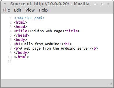
Web Page HTML Code (Markup)
HTML and other web page code is explained in the next part of this tutorial.
← Go back to Part 1Go to Part 3 →
Шилды Ethernet Shield для Arduino Uno или Nano
Наиболее удобным способом работы с W5100 является использование готовых шилдов Ethernet Shield для Arduino Uno или Nano. На таких модулях уже выполнены все необходимые обвязки, шилд просто вставляется в соответствующие разъемы платы и вам остается только загрузить скетч. Естественно, что при желании к плате могут быть подключены и другие устройства.
Arduino Ethernet Shield
Подключение платы расширения происходит через соединение RJ-45. Плата обладает встроенным слотом SD/MicroSD , который используется для хранения файлов, используемых для подключения и передачи по локальной сети. Такой слот совместим со всеми платами Arduino/Genuino, т.е. работать с данными на карте можно с помощью стандартной библиотеки SD Library. На плате расширения также можно найти кнопку перезагрузки . питания. Ранние версии платы расширения не дружили с ардуино мега, там требовался ручной сброс после поступления питания.
Если плата оснащена POE модулем (питание подается по витой паре), то шилд будет соответствовать следующим спецификациям:
- Совместим со стандартом IEEE3af.
- Имеет низкие пульсации на выходе.
- Защищает от явлений перегрузки и короткого замыкания.
- Эффективно преобразует напряжение.
- Имеет изоляцию 1500 вольт на точке между «вход-выход»
По умолчанию плата не комплектуется данным модулем, нужно находить соответствующую модель.
Назначение светодиодов Ethernet Shield:
- PWR показывает наличие питания на плате.
- LINK светится при наличии сети и мигает при передаче/приеме данных.
- FULLD обозначает сетевое полнодуплексное соединение.
- 100M обозначает сетевое соединение со скоростью 10мбит/сек.
- RX мигает при приеме экраном данных.
- TX мигает при отправке данных экраном.
- COLL мигает при обнаружении сетевых конфликтов.
Кроме этих имеются еще пара светодиодов на гнезде rj 45, один из которых при подключенном шнуре светится, а другой мерцает при поступлении данных.
Ehternet для Arduino Nano
Отдельного упоминания заслуживает модуль Arduino Nano Ethernet. Он выполнен в формфакторе, облегчающим подключение к плате Nano v 3.0, но обладает практически такими же возможностями, что и “обычный” вариант для Uno. В основе шилда лежит микросхема ENC28J60.
Шилд Ethernet Arduino Nano Shield
Модуль точно так же имеет разъем RJ-45, слот для SD и в некоторых модификациях тоже оснащен PoE контроллером.
Режимы работы ESP8266
Одна из важнейших функций, которую обеспечивает ESP8266, заключается в том, что он может не только подключаться к существующей Wi-Fi сети и работать в качестве веб-сервера, но он также может устанавливать собственную сеть, позволяя другим устройствам подключаться непосредственно к нему и получать доступ к веб-страницам. Это возможно, потому что ESP8266 может работать в трех разных режимах: режим станции, режим точки доступа и оба первых режима одновременно. Это обеспечивает возможность построения ячеистых сетей.
Режим станции (STA)
ESP8266, который подключается к существующей сети W-iFi (созданной вашим беспроводным маршрутизатором), называется станцией (Station, STA).
Рисунок 2 – Демонстрация режима Station ESP8266 NodeMCU
В режиме STA ESP8266 получает IP адрес от беспроводного маршрутизатора, к которому подключен. С этим IP адресом он может настроить веб-сервер и выдавать веб-страницы на все подключенные к существующей Wi-Fi сети устройства.
Режим точки доступа (AP)
ESP8266, который создает свою собственную сеть Wi-Fi и действует как концентратор (точно так же как маршрутизатор Wi-Fi) для одной или нескольких станций, называется точкой доступа (Access Point, AP). В отличие от Wi-Fi роутера, он не имеет интерфейса к проводной сети. Такой режим работы называется Soft Access Point (soft-AP). Максимальное количество станций, которые могут к нему подключиться, ограничено пятью.
Рисунок 3 – Демонстрация режима Soft Access Point ESP8266 NodeMCU
В режиме AP ESP8266 создает новую сеть Wi-Fi и устанавливает для нее SSID (имя сети) и присваивает себе IP адрес. По запросу на этот IP адрес он может выдавать веб-страницы всем подключенным к этой сети устройствам.
ALGORITHM:
- Input “AT+RST” command and wait until ESP8266 connects with AP.
- Check for “IP\r\n” in the last four characters of ESP response, this indicate that WiFi got IP.
- Once connected start feeding the commands to activate the server mode in ESP8266
- Monitor the response for each input commands.
- Proceed with the next command once the last four characters of response is “OK\r\n” throughout the Server sequence commands.
- Force Arduino to wait for the client request from any browser connected within the LAN.
- Once request is received check for connection ID provided by ESP8266 and add it to the command “AT+CIPSEND”
- Check for the character ‘>’ in the response string from EP module.
- In case of incorrect response repeat step 7.
- Once correct response is verified send the webpage HTML code from Arduino through the ESP module to client browser.
- Wait until you receive response from ESP8266 module and check for the last four characters “OK\r\n” in the response string. Webpage should have been successfully displayed in the browser now.
- Force Arduino to monitor the incoming GET request from Client (button press)
- Once client GET request is received check for URL parameters in the request, for example GET: /ON , in which /ON is the URL parameter.
- Activate/ Deactivate LED/ other devices or do something based on the URL parameter in the response.
Похожие записи:
 Светодиодные прожекторы на 50 вт: обзор моделей и цены
 Расчет освещенности помещения со светодиодными светильниками
 Обозначения постоянного и переменного тока: ac и dc ток
 Как выбрать узо + рейтинг лучших производителей
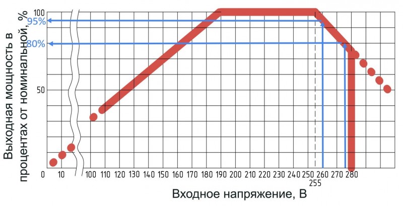 Как защитить компьютер или ноутбук от плохой сети 220в. и надо ли защищать?
 Поезда на магнитной подушке