Set your Goal and make an estrategy
There is a few routines in the Internet to manage the Si5351 chip, all of them has a few distinct feature set because they use different strategies (different goals) that make them unique in some way.
My goal is this:
- Keep it as small as possible (Smallest firmware footprint)
- Less phase and click noise possible (Playing with every trick possible)
- Make it as fast as possible (thanks to @birdwes for I2C busrt mode write)
The main purpose is to be used in Radio receiver projects, so this two mentioned goals are the golden rule.
Let’s list some of goals achievements and bonuses:
Small firmware footprint:
A basic sketch to set just only one clock out to a given frequency with a change in power and correcting the XTAL ppm error is only ~3.3 kBytes of firmware (~10% of an Arduino Uno)
The same settings with the Si5351Arduino library (Etherkit) will give you a bigger firmware space of ~10 kBytes or 31% of an Arduino Uno.
Jerry Gaffke embedded routines in the ubitx transceiver has the smallest footprint in the Arduino platform I have seen, but has worst phase noise and smallest frequency range.
Phase noise to the minimum:
We use every trick on the datasheet, OEM Application Notes or the Internet to minimize phase noise. (Even a few ones learned on the process)
For example the Etherkit library and Jerry Gaffke embedded routines uses some but not all the tricks to minimize phase noise (Etherkit one gives control over all features, Jerry Gaffke has small footprint and in the process he sacrifice phase noise and frequency range)
Click noise free:
If you play from the book (Datasheet and Application Notes) you will have a «click-like» noise burst every time you change the output frequency.
That’s not a problem if you intend to use only fixed frequencies at the output, but if you plan to sweep or use it on any application that moves the frequency that click-like noise will haunt you. (like in a radio receiver or transceiver)
I have learned a few tricks from many sources in the Internet and after some local testing I have came across a scheme that make this lib virtually click-noise-less; see the «Click noise free» section below for details.
Fast frequency changes:
This was a side effect of the last trick to minimize the click noise, see the «Click noise free» section below for details; also with the I2C busrt write contribution from @birdwes even the I2C writes takes a lot less time (implemented since version 0.7.0)
Summary: other routines write all registers for every frequency change, one byte at a time; I write half of them most of the time and in a bust mode speeding up the process a lot.
Two of three
Yes, there is no such thing as free lunch, to get all the above features and the ones that follow I have to make some sacrifices, in this case spare one of the outputs. See «Two of three» section below.
Hardware Requirements and Setup
This library has been written for the Arduino platform and has been successfully tested on the Arduino Uno and an Uno clone. There should be no reason that it would not work on any other Arduino hardware with I2C support.
The Si5351 is a +3.3 V only part, so if you are not using a +3.3 V microcontroller, be sure you have some kind of level conversion strategy.
Connect a 25 MHz or 27 MHz crystal with a load capacitance of 6, 8, or 10 pF to the Si5351 XA and XB pins. Locate the crystal as close to the Si5351 as possible and keep the traces as short as possible. Please use a SMT crystal. A crystal with leads will have too much stray capacitance.
Addendum April 4, 2018: Amplitude Modulation Experiment
I thought I might try generating an AM modulated signal by summing three generator outputs. A 1.1 MHz signal modulated at 1 KHz would have a 1.100 MHz carrier, a 1.101 MHz upper sideband at half the carrier amplitude, and a 1.099 MHz sideband at half the carrier amplitude. I breadboarded a resistive combiner as follows:
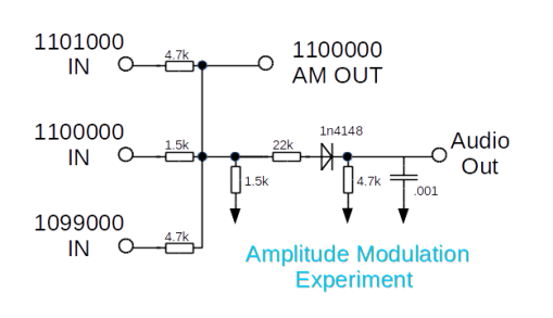
Resistive Combiner
The Si5351 was set to equal drive power on all three outputs. I examined the output on the oscilloscope, channel 1 connected to AM Out, channel 2 to Audio Out with sync taken from Channel 2. The result is not encouraging. It does output an amplitude modulated signal but the waveforms are bizarre. I see a blocky square wave changing at a 1000 Hz rate but there is some phase problem I can’t control. This is the best I could capture:
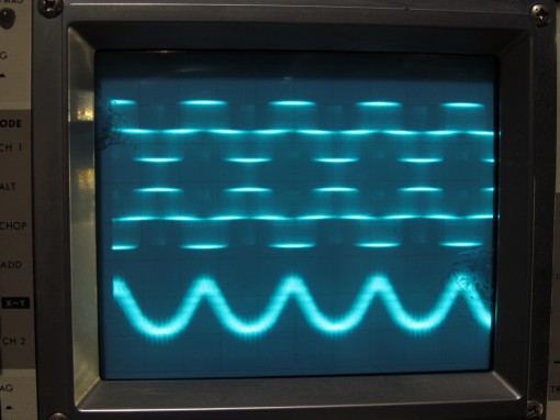
AM Modulated Signal
Connecting an audio amp and speaker does show a 1 KHz tone if the phases happen to line up just right. I found that setting any one of the generators to be one Hz off frequency results in a rolling pattern with about a one per second beat note in the speaker.
This method of faking Amplitude Modulation is certainly not precise or controllable. Setting one of the outputs off frequency by a few Hz does give a useful warbling tone in an AM receiver.
Example 1: using bit-banged I2C
Click to download files:
| main.c | contains main() function — just a call to si5351aSetFrequency(10000000); which sets Clk0 to 10MHz |
| si5351a.c | my si5351a demo library that calculates and sets the Si5351a registers |
| si5351a.h | header file for the si5351a demo library |
| i2cmaster.s | Peter Fleury’s assembly-language bit-banged I2C library, slightly modified (see text below) |
| i2cmaster.h | header file for Peter Fleury’s bit-banged I2C library |
My example here is actually set up so that it runs on the ATmega328 in my Ultimate3S QRSS/WSPR transmiter kit. In that kit the AVR’s actual I2C (TWI) peripheral pins are connected to other stuff. The kit is designed for backward compatibility with the earlier AD9850 DDS module, and other I/O pins are used to program the AD9850 DDS tuning word. It’s a good example of using the bit-banged approach.
main.c just contains a call to si5351aSetFrequency(10000000); which sets the frequency to 10MHz. You can specify any value from 1MHz to 150MHz.
si5351a.c is where all the hard work goes on, to determine the correct register entries to configure the Si5351A to get the desired output frequency. There are some comments in the code to explain it. The comments are nicely tab-indented to character column 37 in my AVR Studio, but they might not line up so nicely in your editor or your internet browser.
si5351a.h is just the header file for si5351a.c — note that I kept it minimal. I have not created a #define for every register the Si5351A has, or tried to cater for all the functionality or variants of the Si5351 chip. Unlike other Si5351A demo libraries, I want to keep this one as simple and easy to understand as possible. So I only created #defines for things I needed. You do have #defines for the clock configuration registers, for the base address for PLL A and B, and for the base addresses for multisynth 0, 1 and 2; as well as the R-Divider definitions for division ratios 1..128. There is also XTAL_FREQ which is defined as 27,000,000 to match the 27MHz crystal on the Si5351A Synth module kit. The actual oscillation frequency will be different. I have one here which measures 27,004,417 for example. If precision is important to your application, you will want to measure and put in the actual oscillation frequency here.
i2cmaster.s is Peter Fleury’s assembly-language bit-banged I2C library. I made three changes for this application: I installed the Si53451A Synth module in my Ultimate3S QRSS/WSPR transmitter kit, as a convenient hardware platform to use for this demo.
Firstly, the i2cmaster.s as it came, has its i2c_delay_T2 set up to generate a 5us timing delay with a 4MHz clock. My system had a 20MHz clock, so I just added a bunch more «rjmp» instructions to add more delay, to make it 5us even with the 20MHz system clock. You might need to configure this for your system. This all assumes a 100kHz I2C bus but in reality this doesn’t need to be that precise.
Secondly, I adapted the section that specifies what I/O pins to use for the bit-banged I2C:
;***** Adapt these SCA and SCL port and pin definition to your target !!
;
#define SDA_PORT	PORTD		// SDA Port D
#define SDA		2		// SDA Port D, Pin 2

#define SCL_PORT	PORTB		// SCL Port B
#define SCL		1		// SCL Port B, Pin 1
This needs to be altered to suit your hardware configuration. In my case I am using the Ultimate3S QRSS/WSPR transmitter kit as a test/demo hardware platform, so I chose the Port and Pins which happen to be connected to the Si5351A module’s SDA and SCL pins.
Thirdly, I also added an i2c_exit() function. The documentation for this library includes an i2c_init() function which it says needs to be called only once. However, that assumes you want to use the 2 I/O signals of the processor ONLY for behaving as an I2C bus to control the Si5351A. But, maybe your system is more complex than that, and you want to dual-purpose I/O pins to control other things too (like in the Ultimate3S QRSS/WSPR transmitter kit). So I added the i2c_exit() function; then in the examples above I call i2c_init() at the beginning of the functions, and i2c_exit() at the end. This way, the pins can be used for other things (carefully), and are only owned by the I2C Si5351A communication while actually in use.
i2cmaster.h is the header file for i2cmaster.s and I didn’t need to modify it, apart from the definition of the i2c_exit function.
Features
This are so far the implemented features (Any particular wish? use the Issues tab for that):
- Custom XTAL passing on init (Default is 27.000 MHz (See Si.init() )
- You can pass a correction to the xtal while running (See Si.correction() )
- You have a fast way to power off all outputs of the Chip at once. (See Si.off() )
- You can enable/disable any output at any time (See Si.enable(clk) and Si.disable(clk) )
- By default all outputs are off after the Si.init() procedure. You has to enable them by hand.
- You can only have 2 of the 3 outputs running at any moment (See «Two of three» section below)
- Power control on each output independently (See Si.setPower(clk, level) on the lib header)
- Initial power defaults to the lowest level (2mA) for all outputs.
- You don’t need to include and configure the Wire (I2C) library, this lib do that for you already.
- I2C writes are handled in busrt mode, just init the I2C once per frequency change and dump the registers content and close; saving the init for each byte sent as normal.
- Frequency limits are not hard coded on the lib, so you can stress your hardware to it’s particular limit (You can move usually from ~3kHz to ~225 MHz, far away from the 8kHz to 160 MHz limits from the datasheet)
- You has a way to verify the status of a particular clock (Enabled/Disabled by the Si.clkOn var)
- From v0.5 and beyond we saved more than 1 kbyte of your precious firmware space due to the use of all integer math now (Worst induced error is below +/- 1 Hz)
- Overclock, yes, you can move the limits upward up to ~250MHz (see the «OVERCLOCK» section below)
- Improved the click noise algorithm to get even more click noise reduction (see Click noise free section below)
- Fast frequency changes as part of the improved click noise algorithm (see Click noise free section below) & I2C writes in burst mode.
Adding OLED to SummitProwler VFO/Controller script
All the VFO/Controllers in my homebrew radios use the same script, available here. Each time I use it in a new receiver or transceiver project, I isolate the project-specific code with a #define‘d project label and #ifdef #endif pairs. This ensures only the code required for that project is included in the compiler scope. This is mostly around the UpdateDisplay() method, BFO initialisation, encoder and push-buttons. Most of the VFO, T/R, rig control, metering and keyer code is common. Some code (e.g. PCF8574 drivers for band switching) is small and is left in, even if not used.
After pasting in the SSD1306 code, and wrapping with pre-processor directives, the script settled at 93% program space and 73% global variable space. Code space on the edge of the warning, so there might be some refactoring to be done soon, as I seem to keep adding features!
The Box
A thin metal gift card box was cut up to form an enclosure for the generator. It is about a quarter inch larger than the usual Altoids tin in all three dimensions. I needed the extra volume to fit in a battery and charger removed from a cheap phone power pack. These booster packs usually contain a single 18650 cell and it just fits.
Arduino-Si5351 Signal Generator Interior
The components are, top to bottom, blue 16×2 LCD board supporting the Teensy-LC. The entire unit can be 5 volt powered either from the Teensy USB jack or from the battery charger, I added a fat diode to isolate the two sources. Both the Teensy and the Si5351 board are using their on board voltage regulators. The LCD is five volt, but the Teensy-LC does not have 5 volt tolerant inputs. There are 2.2k resistors between the LCD data pins and the Teensy to smooth over that discrepancy, these would not be necessary if the LCD was a 3.3 volt unit. The pot below the Teensy adjusts the LCD contrast.
At left below the LCD is the Adafruit (Bourns) rotary encoder. It just clears the battery. Right of the encoder is a strip of perf board with the three output select pushbuttons mounted. The LCD, encoder and buttons are Adafruit parts.
At the top of the open box bottom is the salvaged 18650 cell. The measured drain of the whole circuit is less than 100 milliamps so the battery should last half a day at least. The gooey glob at the center is a 2.5 amp fuse. To the right of the battery is the on/off switch and isolation diode. The salvaged Lithium charge/boost circuit is the green board at bottom right. It has it’s own separate USB jack because the USB data leads are not accessible. To program the unit you have to plug into the Teensy USB jack.
Finally the blue board in the bottom is the Etherkit breakout. The actual Si5351 chip is at the left end, next to the TCXO. There are three RCA output jacks mounted in the left side of the box, the fourth jack next to the handle is for syncing the scope when sweeping.
OVERCLOCK
Yes, you can overclock the Si5351, the datasheet states that the VCO moves from 600 to 900 MHz and that gives us a usable range from ~3 kHz to 225 MHz.
But what if we can move the VCO frequency to a higher values?
The overclock feature does just that, use a higher top limit for the VCO on the calculations. In my test with two batch of the Si5351A I can get safely up to 1.000 GHz without trouble; in one batch the PLL unlocks around 1.1 GHz and in the other about 1.050 GHz; so I recommend not going beyond 1.000 GHz.
With a maximum VCO of 1.000 GHz and a lower division factor of 4 we have jumped from a 225 MHz to 250 MHz top frequency that can be generated with our cheap chip.
Some «must include» WARNINGS:
- The chip was not intended to go that high, so, use it with caution and test it on your hardware moving the overclock limit in steps of 10 MHz starting with 900 MHz and testing with every change until it does not work; then go down by 10 MHz to be in a safe zone.
- Moving the upper limit has its penalty on the lower level, your bottom frequency will move from the ~3 kHz to ~10 kHz range.
- The phase noise of the output if worst as you use a higher frequency, at a fixed 250 MHz it’s noticeable but no so bad for a TTL or CMOS clock application.
- The phase noise is specially bad if you make a sweep or move action beyond 180 MHz; the phase noise from the unlock state to next lock of the PLL is very noticeable in a spectrum analyzer, even on a cheap RTL-SDR one.
- I recommend to only use the outputs beyond 150 MHz as fixed value and don’t move them if you cares about phase noise.
How to do it?
You need to declare a macro with the overclock value BEFORE the library include, just like this:
Postscripts
August 2017: I made up a second Arduino Nano and si5351 VFO/BFO/Controller for another homebrew rig, with some improvements. The post describing the VFO is here. A video of the new rig (receiver only at this stage) is here.
March 2018: Have built four or five Arduino Nano/si5351 VFO/Controllers now. A post describing my latest Nano/si5351 controlled QRP rig is here.
September 2018: Here’s a post on a compact G6LBQ BiTx using an Arduino/si5351 VFO and BFO.
November 2018: Here’s the github repo with my code. It works on a HFSignals (VU2ESE) Raduino module. If you use it, remember to execute the Initialiser script once (to set up EEPROM). Further details in the readme and main file header.
December 2018: And another Arduino/si5351 compact VFO/BFO/Controller and CW Keyer, first stage of a compact multiband SSB/CW transceiver.
Микросхема (модуль) Si5351
Микросхема Si5351 это конфигурируемый через I2C генератор тактовых частот, идеально подходящий для замены кварцев, кварцевых генераторов, генераторов VCXO (voltage-controlled crystal oscillator – кварцевый генератор, управляемый напряжением), синтезаторов с ФАПЧ (PLL), буферов развязки в приложениях, критичных к общей стоимости. Базируясь на архитектуре PLL/VCXO + high resolution MultiSynth fractional divider, Si5351 может генерировать любую частоту до 200 МГц на каждом из выходов с нулевым отклонением от заданного значения (0 ppm error). Для удовлетворения различным требованиям приложений Si5351 выпускается в 3 версиях. Si5351A генерирует до 8 не зависящих друг от друга тактовых сигналов, используя внутренний генератор, что позволяет заменить несколько кварцев или кварцевых генераторов. В Si5351B добавлен внутренний VCXO, что дает возможность заменить как свободно (независимо друг от друга), так и синхронно генерируемые тактовые частоты. Это устраняет необходимость применения дорогих специальных кварцев, предоставляя при этом высокую надежность работы в широком диапазоне настраиваемых частот. Si5351C предоставляет такую же гибкость, но синхронизируется при этом с внешним опорным генератором (CLKIN).
Узнать более подробную информацию о микросхеме Si5351 и ее подключение к плате Arduino вы можете на сайте ее разработчика. Также принципы ее работы неплохо описаны на сайте microsin.net.
Sweep Function
Sweep is accessed from a separate menu. Press down the encoder knob for more than two seconds (a long press) and release to enter sweep parameters for the currently selected port. A short click of the encoder knob will advance the menu through the sweep choices, currently +/- 0, 1000, 5000, 15000, 50000, or 150000 Hz. The unit sweeps from frequency minus that amount to frequency plus that amount so the total width of sweep is twice the setting. Sweeping is done by reprogramming frequencies in 20 steps between the limits.
A second long press of the encoder knob will return to the frequency menu. The letters “sw” appear on the LCD to indicate that that port is set up to sweep. All three ports can be set up but only the port currently selected in the display will be sweeping at any given time.
A pulse is available at a phono jack on top of the box to trigger an oscilloscope at start of each sweep iteration.
Sweep parameters are not currently saved in EEPROM.
Arduino-Si5351 Signal Generator Sweep Setup Screen
How to use the lib
Get the lib by cloning this git repository or get it by clicking the green «Download button» on the page.
Move it or extract it on your library directory
Include the lib in your code:
Follow this sequence on you setup() procedure:
- Initialize the library with the default or optional Xtal Clock.
- Apply correction factor (if needed)
- Set some frequencies to the desired outputs.
- Enable the desired outputs
Here you have an example code («Si» is the lib instance):
If you need to apply/vary the correction factor after the setup process you will get a click noise on the next setFreq() to apply the changes.
Use it, you can enable, disable, change the power or frequency, see this code fragment with some examples:
A Brief Word about the Si5351 Architecture
The Si5351 consists of two main stages: two PLLs which are locked to the reference oscillator (a 25/27 MHz crystal) and which can be set from 600 to 900 MHz, and the output (multisynth) clocks which are locked to a PLL of choice and can be set from 500 kHz to 200 MHz (per the datasheet, although it does seem to be possible to set an output up to 225 MHz).
The B variant has an additional VCXO stage with control voltage pin which can be used as a reference synth for a clock output (PLLB must be used as the source for any VCXO output clock).
The C variant is able to take a reference clock input from 10 to 100 MHz separate from the standard crystal reference. If using this reference input, be sure to initialize the library with the correct frequency.
This library makes PLL assignments based on ease of use. They can be changed manually if needed, although that can introduce complications (see Manually Selecting a PLL Frequency below).
Миниатюрный синтезатор (Si5351)
Andrew Woodfield, ZL2PD
Cинтезаторы частоты на основе микросхемы Si5351 достаточно популярны, благодаря низкой стоимости и широкому диапазону частот (вплоть до УКВ диапазона). На своем сайте я уже рассказывал о синтезаторе на этой микросхеме. А здесь хочу рассказать ещё об одной очень простой конструкции.
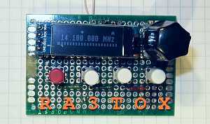
Радиолюбитель и программист из Новой Зеландии Andrew Woodfield (ZL2PD) представил на своем сайте очередную версию синтезатора весьма компактного размера, не превышающего размер кубика сахара, что и послужило его названию «SugarCube Si5351 VFO».
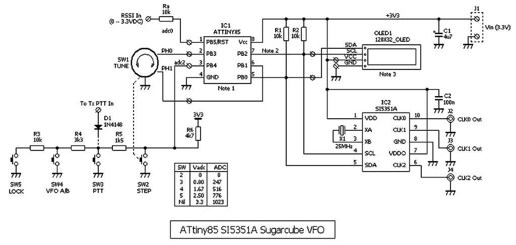
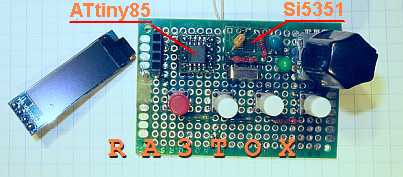
Управление синтезатором осуществляется микропроцессором ATtiny85, а информация отображается на миниатюрном OLED дисплее. Несмотря на малый объем памяти процессора и весьма ограниченное количество портов, автору удалось создать полноценный синтезатор для трансивера с весьма богатым набором функций:
Информация, выводимая на дисплей синтезатора: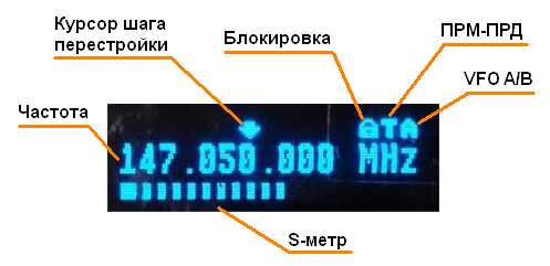
В качестве примера автор предложил три разные версии программного обеспечения с несколькими возможностями:
Версия A: Стандартный VFO для типичного приемопередатчика с ПЧ 8,87 МГц
Версия B: Стандартный VFO для типичного трансивера, который не требует смещения ПЧ
Версия C: VFO для УКВ для приемника с ПЧ 10,7 МГц
Программное обеспечение написано на языке Bascom для семейства микроконтроллеров Atmel. Его компилятор достаточно эффективен, и, как можно видеть, полученный код довольно компактен. Исходники автор не выложил. Доступны только HEX-файлы для прошивки трех версий.
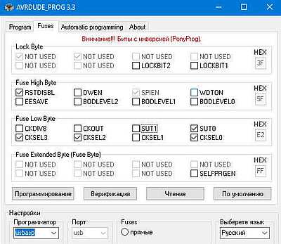
В связи с ограниченным количеством выводов у микропроцессора, пришлось задействовать вывод RESET. Поэтому следует помнить, что перепрограммировать процессор стандартным способом не получится — потребуется высоковольтный программатор (HV).
Также в статье автора подробно описан процесс сборки синтезатора. Приводится документация для изготовления печатной платы (Gerber-файлы). Также приведены подробные примеры оспользования синтезатора.
Моя конструкция (RA3TOX)
Собрал этот синтезатор за один вечер. Малое количество деталей позволяет выполнить всё устройство на макетной плате. Микросхемы распаяны на отдельных переходниках. OLED дисплей на разъеме. Конструкция у меня получилась размером со спичечный коробок. Прошивку микроконтроллера сделал программатором USBASP. Запитал синтезатор от USB адаптера через микросхему стабилизатора ASM1117-3,3V. Всё заработало без проблем! Как недостаток, можно отметить отсутствие переключателя диапазов. Приходится устанавливать шаг настройки в 1 МГц и переключать выше или ниже по частоте. Возможно автору не хватило ресурсов процессора для реализации данной функции.
Материал перевёл и подготовил Николай Большаков (RA3TOX).
Сентябрь 2019 .
Setting the Output Frequency
As indicated above, the library accepts and indicates clock and PLL frequencies in units of 0.01 Hz, as an unsigned long long variable type (or uint64_t). When entering literal values, append to make an explicit unsigned long long number to ensure proper tuning. Since many applications won’t require sub-Hertz tuning, you may wish to use an unsigned long (or uint32_t) variable to hold your tune frequency, then scale it up by multiplying by 100ULL before passing it to the set_freq() method.
Using the set_freq() method is the easiest way to use the library and gives you a wide range of tuning options, but has some constraints in its usage. Outputs CLK0 through CLK5 by default are all locked to PLLA while CLK6 and CLK7 are locked to PLLB. Due to the nature of the Si5351 architecture, there may only be one CLK output among those sharing a PLL which may be set greater than 100 MHz (actually specified at 112.5 MHz by SiLabs, but stability issues have been found at the upper end). Therefore, once one CLK output has been set above 100 MHz, no more CLKs on the same PLL will be allowed to be set greater than 100 MHz (unless the one which is already set is changed to a frequency below this threshold).
If the above constraints are not suitable, you need glitch-free tuning, or you are counting on multiple clocks being locked to the same reference, you may set the PLL frequency manually then make clock reference assignments to either of the PLLs.
Using an External Reference (Si5351C)
Please see the example sketch si5351_ext_ref.ino
The Si5351C variant has a CLKIN input (pin 6) which allows the use of an alternate external CMOS clock reference from 10 to 100 MHz. Either PLLA and/or PLLB can be locked to this external reference. The library tracks the referenced frequencies and correction factors individually for both the crystal oscillator reference (XO) and external reference (CLKIN).
The XO reference frequency is set during the call to init(). If you are going to use the external reference clock, then set its nominal frequency with the set_ref_freq() method:
A correction factor for the external reference clock may also now be set:
The set_pll_input() method is used to set the desired PLLs to reference to the external reference signal on CLKIN instead of the XO signal:
Once that is set, the library can be used as you normally would, with all of the frequency calculations done based on the reference frequency set in set_ref_freq().
Oddities
The Si5351 datasheet specifies an I2C address of 0b1100000 (0x60), but this has not been the correct address on the samples used at the NT7S lab. Using the Bus Pirate’s I2C address scan macro, we have determined that the address that the Si5351A wants to see is 0x6F (0xDE in 8-bit format), so that is what we use in the library. If you have trouble communicating with your Si5351, you may want to adjust this value in the si5351.h file back to the specified value (0xC0 in 8-bit format). Given the high number of errors we have found in the datasheet so far, this is unsurprising.
Update: It turns out that we were sent defective parts. Another batch was ordered from a different vendor and they work on the proper I2C address of 0x60. The code has been updated to reflect the correct address.
Right now, this code is focused solely on the 3-output 10-MSOP variant (Si5351A3). Since some of the code was derived from the Si5351 driver in the Linux kernel, it may be useable on with the other variants, but certainly many features won’t work yet. With any luck, we will get the library to work with the other variants as well, or even better, maybe someone will take the initiative, write the code, and send me a pull request.
Общие принципы работы проекта
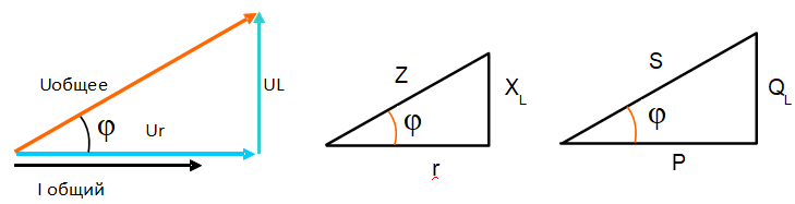
В данном проекте рассматривается генератор перестраиваемой частоты (variable-frequency oscillator, VFO), пригодный для использования в «домашних» (Do It Yourself , DIY) условиях. Этот генератор может пригодиться в синтезаторах частоты, супергетеродинных радиоприемниках, SDR-приемопередатчиках и т.д. Генератор имеет шкальный индикатор (Bargraph indicator) для отображения мощности сигнала (S-Meter) и 20 заранее установленных диапазонов частот.
Основные особенности проекта:
- рабочий диапазон от 10 кГц до 225 МГц;
- шаг настройки: 1 Гц, 10 Гц, 1 кГц, 5 кГц, 10 кГц и 1 МГц;
- регулируемое смещение (+ или -) промежуточной частоты (ПЧ);
- 20 заранее установленных диапазонов частот (с быстрым доступом) в полосах частот АМ-вещания (BCB) и радиолюбительских диапазонах (HAM frequencies);
- режим генерации сигналов (функциональный генератор);
- для использования в качестве местного генератора на самодельных супергетеродинных радиоприемниках или радиоприемниках с прямым преобразованием;
- для использования в качестве генератора переменной частоты для радиолюбителей;
- для использования в качестве простого тактового генератора для калибровки или генерации тактовых импульсов;
- шкальный индикатор для отображения мощности сигнала через вход АЦП (аналого-цифрового преобразователя);
- возможность работы с платами Arduino Uno, Nano и Pro Mini;
- использует стандартный дисплей 128×64 I2C OLED SSD1306 и модуль Si5351;
- передача данных по интерфейсу I2C, необходимо всего 2 провода для подключения дисплея и модуля Si5351 к плате Arduino;
- высокая стабильность и точность генерации частоты;
- хорошая эффективность, невысокая стоимость, можно собрать в домашних условиях.
Library Installation
The best way to install the library is via the Arduino Library Manager, which is available if you are using Arduino IDE version 1.6.2 or greater. To install it this way, simply go to the menu Sketch > Include Library > Manage Libraries…, and then in the search box at the upper-right, type «Etherkit Si5351». Click on the entry in the list below, then click on the provided «Install» button. By installing the library this way, you will always have notifications of future library updates, and can easily switch between library versions.
If you need to or would like to install the library in the old way, then you can download a copy of the library in a ZIP file. Download a ZIP file of the library from the GitHub repository by using the «Download ZIP» button at the right of the main repository page. Extract the ZIP file, then rename the unzipped folder as «Si5351». Finally, open the Arduino IDE, select menu Sketch > Import Library… > Add Library…, and select the renamed folder that you just downloaded. Restart the IDE and you should have access to the new library.
Example
First, install the Si5351Arduino library into your instance of the Arduino IDE as described above.
There is a simple example named si5351_example.ino that is placed in your examples menu under the Si5351Arduino folder. Open this to see how to initialize the Si5351 and set a couple of the outputs to different frequencies. The commentary below will analyze the sample sketch.
Before you do anything with the Si5351, you will need to include the «si5351.h» and «Wire.h» header files and instantiate the Si5351 class.
Now in the Setup() function, let’s initialize communications with the Si5351, specify the load capacitance of the reference crystal, that we want to use the default reference oscillator frequency of 25 MHz (the second argument of «0» indicates that we want to use the default), and that we will apply no frequency correction at this point (the third argument of «0»):
The init() method returns a bool which indicates whether the Arduino can communicate with a device on the I2C bus at the specified address (it does not verify that the device is an actual Si5351, but this is useful for ensuring that I2C communication is working).
Next, let’s set the CLK0 output to 14 MHz:
Frequencies are indicated in units of 0.01 Hz. Therefore, if you prefer to work in 1 Hz increments in your own code, simply multiply each frequency passed to the library by 100ULL (better yet, use the define called SI5351_FREQ_MULT in the header file for this multiplication).
In the main Loop(), we use the Serial port to monitor the status of the Si5351, using a method to update a public struct which holds the status bits:
When the synthesizers are locked and the Si5351 is working correctly, you’ll see an output similar to this one (the REVID may be different):
The nominal status for each of those flags is a 0. When the program indicates 1, there may be a reference clock problem, tuning problem, or some kind of other issue. (Note that it may take the Si5351 a bit of time to return the proper status flags, so in program initialization issue update_status() and then give the Si5351 a few hundred milliseconds to initialize before querying the status flags again.)
Simple example code
The example code is written in C for AVR microcontrollers, I use the GCC compiler in AVR Studio. It should be easy to use this on any AVR, or on the Arduino platform. Only minor changes would be needed for other microcontrollers.
There are TWO examples here. The first example allows you to use ANY I/O pins of the processor to bit-bang as I2C. That gives a lot of flexibility, if you happen to be using I/O pins other than the AVR’s onboard I2C peripheral (they call it the Two Wire interface in the Atmel datasheets and application notes), or if you are using an AVR device that doesn’t have an I2C peripheral onboard: not all support I2C. In this example we use a very nice assembly language library by Peter Fleury to take care of the I2C bit-banging. It works perfectly!
The second example uses the AVR’s internal I2C peripheral (which they call the Two Wire interface, TWI, in the datasheets and application notes). That assumes that in your application, your chosen AVR does have a TWI peripheral, and that you aren’t using those particular I2C pins of the processor for something else, so you can afford to dedicate them to I2C purposes. This is the ideal situation.
Похожие записи:
 Светодиодные прожекторы на 50 вт: обзор моделей и цены
 Расчет освещенности помещения со светодиодными светильниками
 Обозначения постоянного и переменного тока: ac и dc ток
 Как выбрать узо + рейтинг лучших производителей
 Как защитить компьютер или ноутбук от плохой сети 220в. и надо ли защищать?
 Поезда на магнитной подушке