Equivalent to Arduino millis()
Hi,
Arduino has the fairly convenient `millis()` function which returns the number of milliseconds since boot. What is the situation for that on mBed. As far as I can tell mBed has these:
clock() — Returns number of CPU ticks, as defined by CLOCKS_PER_SEC. Unfortunately that is a) not constant, and b) not very fine-grained. For example on nRF51822 CLOCKS_PER_SEC is 100.
time_t time(…) — Standard POSIX time call, but unfortunately this just returns 0 on boards without a real RTC.
us_ticker_read() — This always returns microseconds since boot, and is required for mBed, but it has an ugly name and is an internal API.
As mentioned in the answer below, you can make an instance of Timer, but a) you have to manually start it, b) it isn’t global, c) the name of the instance isn’t fixed, d) you have to put it in your own Globals.h header (or similar).
This seems like a sorry situation for mBed’s otherwise great API. I would suggest adding some non-internal functions like this:
float clock_s() { return us_ticker_read() / 1000000.0f; }
uint64_t clock_ms() { return us_ticker_read() / 1000; }
uint64_t clock_us() { return us_ticker_read(); }
Who’s with me? (By the way the name is a bit unfortunate — it could cause confusion with clock() — but I couldn’t think of anything better.)
Recent Articles
-
Learn how to use the TP4056 properly. There’s a right way, and a wrong way, to use it to safely charge Lithium Ion batteries.
-
A tutorial on using the ADS1115 precision 16 bit ADC for low power use.
-
Arduino Nano ISP: How to program an ATmega328P using an Arduino Nano as the ISP programmmer. One common problem: Programming a sketch into the chip without a reset control — solved here.
-
I2C tutorial: Learn all about the 2 wire I2C serial protocol. Learn how easy it is to use, how it works and when to use it…
-
How to test and use an Arduino Joystick including a new library to make it super easy.
-
How to use the MCP4728, a versatile four channel DAC with built in voltage reference.
The MCP4728 chip is a four channel 12 bit DAC, with memory that outputs voltage that you can use for calibration, anywhere you want a fixed voltage.
Мигаем светодиодом без delay()
или всегда ли официальный примеру учат «хорошему».
Обычно это одна из первых проблем с которой сталкивается навичок в микроконтроллерх. Помигал диодом, запустил стандартный скетч blink(), но как только он него возникает желание что-бы контроллер «занимался чем-то еще» его ждет неприятный сюрприз — тут нет многопоточности. Как только он написали где-то что-то типа delay(1000) — обнаруживается что на это строчке «контроллер остановился» и ничего больше не делает (кнопки не опрашивает, датчики не читает, вторым диодом «помигать» не может).
Новичок лезет с этим вопросом на форум и тут же получает ушат поучений: «отказывайтесь от delay()», учитесь работать с millis() и в прочитайте, в конце концов базовые примеры. В частности Мигаем светодиодом без delay()
Приведу его код:
/* Blink without Delay
 2005
 by David A. Mellis
 modified 8 Feb 2010
 by Paul Stoffregen
 */

const int ledPin =  13;      // номер выхода, подключенного к светодиоду
// Variables will change:
int ledState = LOW;             // этой переменной устанавливаем состояние светодиода
long previousMillis = 0;        // храним время последнего переключения светодиода

long interval = 1000;           // интервал между включение/выключением светодиода (1 секунда)

void setup() {
  // задаем режим выхода для порта, подключенного к светодиоду
  pinMode(ledPin, OUTPUT);
}

void loop()
{
  // здесь будет код, который будет работать постоянно
  // и который не должен останавливаться на время между переключениями свето
  unsigned long currentMillis = millis();

  //проверяем не прошел ли нужный интервал, если прошел то
  if(currentMillis - previousMillis > interval) {
    // сохраняем время последнего переключения
    previousMillis = currentMillis;

    // если светодиод не горит, то зажигаем, и наоборот
    if (ledState == LOW)
      ledState = HIGH;
    else
      ledState = LOW;

    // устанавливаем состояния выхода, чтобы включить или выключить светодиод
    digitalWrite(ledPin, ledState);
  }
}
В принципе отправка к этому примеру — вполне правильна. В нем действительно виден стандартный паттерн как нужно выполнять какое-то переодическое действие (или отложенное):
1. Сохраняем время в какую-то переменную
2. В loop() все время смотрим на разницу «текущие-время — сохраненное»
3. Когда эта разница превысила какое-то значение (нужный нам «интервал переодичности»)
4. Выполняем какое-то действие (меняем состояние диода, заново запоминаем «стартовое время и т.п.»)
С задачей «объяснить идею» — пример справляется. Но, с моей точки зрения, в нем есть несколько методологических ошибок. Написание скетчек в подобно стиле — рано или поздно приведет к проблемам.
Итак, что же тут не так?
1. Не экономно выбираем тип переменных
Переменная ledPin у нас объявлена как тип int. Зачем? Разве номер пина может быть очень большим числом? Или может быть отрицательным числом? Зачем под его хранение выделять два байта, когда вполне хватит одного. Тип byte может хранить числа от 0 до 255. Для номера пина — этого вполне хватит.
const byte ledPIN = 13; // номер выхода, подключенного к светодиоду
Этого будет вполне достаточно.
2. А зачем нам переменная для малых чисел?
А зачем нам тут вообще переменая? (пусть и объявленная как const). Зачем тратить такты процессора на чтение переменной? И расходовать еще один байт? Воспользуемся директивой препроцессора #define
#define LED_PIN 13 // номер выхода, подключенного к светодиоду
Тогда еще на этапе компиляции компилятор просто подставить 13-ть везде где в коде используется LED_PIN и не будет выделять отдельных переменных.
3. Тип int опять выбрали как «первое что в голову пришло»?
И опять спотыкаемся на объявлении следующей же переменной. Почему ledState опять int? Кроме того что снова «два байта там где можно один использовать», так еще и «смысловая нагрузка» теряется. Что у нас хранится в переменной? Состояние светодиода. Включен/выключен. Горит/Не горит. Явно же напрашивается тип boolean. По крайней мере до тех пор, пока светодиод у нас может принимать два состояния.
When to use Arduino millis() vs micros()
First of all, the functionality is the same: both millis() and micros() are keeping the time since the Arduino program started.
If your program requires executing actions with a resolution higher than one millisecond, then use micros(). If not, just use millis().
The drawback you get when using micros() is that the time variable overflows much quicker than the millis() variable (about 71 minutes instead of 49 days). It might be a problem, unless you only use the time functionalities to compare previous and current time, like we did above in this post.
All in all, the 2 things to keep in mind are the time resolution, and the duration before an overflow. Knowing that, you should have no more problem when writing an Arduino program using time functionalities!
Ардуино задержка включения / выключения
Для этого занятия нам потребуется:
плата Arduino Uno / Arduino Nano / Arduino Mega.
В этой записи мы рассмотрим только основные характеристики функций задержки, а примеры использования представим в виде небольших скетчей. Для работы вам потребуется только сама плата Ардуино. Начнем обзор с delayMicroseconds Arduino, т.к. данную функцию не часто можно встретить в программах, а также рассмотрим, как заменить задержку delay на millis в программировании Arduino IDE.
Ардуино delayMicroseconds()
Команда delayMicroseconds останавливает выполнение программы на заданное количество микросекунд (в 1 секунде 1 000 000 микросекунд). При необходимости задержки в программе более чем на несколько тысяч микросекунд рекомендуется использовать delay(). Продемонстрируем на простом примере использование функции в скетче для мигания встроенным светодиодом на плате Arduino.
// пример использования delayMicroseconds() для мигания светодиодом
void setup() {
   pinMode(13, OUTPUT);
}

void loop() {
   digitalWrite(13, HIGH);      // подаем сигнал HIGH на выход
   delayMicroseconds(100);  // задержка 100 микросекунд
   digitalWrite(13, LOW);       // подаем сигнал LOW на выход
   delayMicroseconds(100);  // задержка 100 микросекунд
}
Ардуино delay()
Команда delay останавливает выполнение программы на заданное количество миллисекунд (в 1 секунде 1 000 миллисекунд). Во время задержки программы с помощью функции delay(), не могут быть считаны подключенные к плате датчики или произведены другие операции, например, запись в еепром Ардуино данных. В качестве альтернативы следует использовать функцию millis(). Смотри пример далее.
// пример использования delay() для мигания светодиодом
void setup() {
   pinMode(13, OUTPUT);
}

void loop() {
   digitalWrite(13, HIGH);   // подаем сигнал HIGH на выход
   delay(100);                        // задержка 100 миллисекунд
   digitalWrite(13, LOW);    // подаем сигнал LOW на выход
   delay(100);                        // задержка 100 миллисекунд
}
Ардуино millis()
Команда millis возвращает количество прошедших миллисекунд с момента начала выполнения программы. Счетчик времени сбрасывается на ноль при переполнении значения unsigned long (приблизительно через 50 дней). Функция miilis позволяет сделать многозадачность Ардуино, так как выполнение программы не останавливается и можно выполнять параллельно другие операции в скетче.
// пример использования millis() при мигании светодиодом
unsigned long timer;

void setup() {
   pinMode(13, OUTPUT);
   Serial.begin(9600);         // запускаем монитор порта
}

void loop() {
   timer = millis();                 // запускаем отсчет времени

   digitalWrite(13, HIGH);   // подаем сигнал HIGH на выход
   delay(1000);                      // задержка 1 секунда
   digitalWrite(13, LOW);    // подаем сигнал LOW на выход
   delay(1000);                      // задержка 1 секунда

   // выводим количество миллисекунд прошедших с момента начала программы
   Serial.print("Time: ");
   Serial.println(timer);
}
Arduino команды millis, delay, delaymicroseconds
Подготовка Arduino IDE и прошивка
- Загружаем и устанавливаем Arduino IDE.
- Распаковываем скачанное в папку с библиотеками Arduino IDE (обычно это C:\Users\<Текущий пользователь>\Documents\Arduino\).
- Копируем полученный код в Arduino IDE.
- В примере вводим фактическое название нашей WiFi-сети и пароль.
В примере также присутствует функция вида:
BLYNK_WRITE(V1)
{
  int pinValue = param.asInt(); // assigning incoming value from pin V1 to a variable

  // process received value
}
Здесь:
- BLYNK_WRITE(V1) указывает, что функция выполнится при изменении виртуального пина 1,
- int pinValue = param.asInt(); объявляет переменную pinValue и загружает в неё текущее состояние виртуального пина (0 — пин выключен, 1 — пин включен).
Всего можно использовать 256 виртуальных пинов (V0-V255) — это огромный запас на все случаи жизни. Например, виртуальный пин 1 принимает значение 1 — подаём питание на физический пин NodeMcu и включаем этим реле, или виртуальный пин 2 принимает значение от 0 до 255 — изменяем ШИМ-сигнал, регулируем яркость (либо цвета RGB) диодной подсветки в 255 градациях яркости.
А теперь заставим нашу функцию включать физический пин D4 NodeMcu (в функции будем использовать событие виртуального пина 0, просто для удобства):
BLYNK_WRITE(V0)
{
  int pinValue = param.asInt();
  digitalWrite('''D4''', pinValue);
}
Чтобы управлять этим выводом, в основной функции void setup() обязательно установим пин D4 как выход: pinMode(D4, OUTPUT);
В итоге получаем такой код для прошивки:
#define BLYNK_PRINT Serial
#include <ESP8266WiFi.h>
#include <BlynkSimpleEsp8266.h>

char auth[] = "Мой токен"; //тут токен из e-mail

char ssid[] = "YourNetworkName"; //Название WiFi-сети
char pass[] = "YourPassword"; //Пароль

BLYNK_WRITE(V0) //функция, отслеживающая изменение виртуального пина 0
{
  int pinValue = param.asInt(); //переменная текущего состояния виртуального пина
  digitalWrite(D4, pinValue); //задаем значение на физическом пине NodeMcu D4 равное значению виртуального пина 0
}

void setup() //основная функция, выполняется один раз при подаче питания на микроконтроллер
{
  Serial.begin(9600); //открываем серийный порт, чтобы видеть как проходит подключение к серверу blynk
  pinMode(D4, OUTPUT); //объявляем D4 "выходным" пином
  Blynk.begin(auth, ssid, pass); //авторизируемся на сервере
}

void loop() //основная функция, которая выполняется постоянно по кругу
{
  Blynk.run(); //запускаем работу blynk. В этом примере - постоянную проверку виртуального пина 0
}
Заливаем прошивку в NodeMcu.
Так как пример предполагает использование различных плат, то пропустим тонкости настройки Arduino IDE для работы с NodeMcu; к тому же подобную информацию найти нетрудно.
Наш выключатель готов к работе!
Также данную схему можно использовать и для включения ПК (имитации нажатия кнопки включения). Для этого параллельно пинам кнопки Power (на материнской плате пины POWER SW) нужно подключить линии L и L1 (указанные на схеме !!!НЕ 220В!!!) и немного изменить скрипт, чтобы при изменении виртуального пина реле включалось на короткий промежуток времени, имитируя короткое нажатие.
В скрипте, в блоке:
BLYNK_WRITE(V0) //функция, отслеживающая изменение виртуального пина 0
{
  int pinValue = param.asInt(); //переменная текущего состояния виртуального пина
  if (pinValue = 0){
     digitalWrite(D4, HIGH); //если работает неверно, то изменить на digitalWrite(D4, LOW); а ниже наоборот
     delay (100); // если задержка мала, можно увеличить
     digitalWrite(D4, LOW); //ДА-ДА, ИМЕННО ТУТ НИЖЕ. Если работает неверно, то изменить на digitalWrite(D4, HIGH);
  }
}
мы добавили задержку delay (100); в 100 мс и выключили после нее физический пин D4 — digitalWrite(D4, LOW);
Кухонный таймер Ардуино с энкодером
Сейчас рассмотрим, как сделать таймер на Ардуино своими руками с энкодером и LCD. Принцип управления, подобен предыдущему варианту. Поворотом ручки энкодера можно задать необходимый временной интервал, а нажатием на ручку можно запускать и останавливать обратный отсчет времени. Далее размещена схема сборки проекта на Arduino Nano, этот проект можно собрать и на плате Arduino Uno.
Скетч таймера обратного отсчета времени
#include <Wire.h>                              // библиотека для протокола I2C
#include <LiquidCrystal_I2C.h>        // библиотека для LCD 1602
LiquidCrystal_I2C LCD(0x27, 20, 2);  // присваиваем имя дисплею

#include <RotaryEncoder.h>                // библиотека для энкодера
RotaryEncoder encoder(4, 2);       // пины подключение энкодера (DT, CLK)

// задаем шаг энкодера, максимальное и минимальное значение
#define STEPS  1
#define POSMIN 0
#define POSMAX 30

int lastPos, newPos;
boolean buttonWasUp = true;

byte w = 0;

int SEC = 0;
int MIN = 0;
unsigned long timer;

void setup() {
   pinMode(6, INPUT_PULLUP);   // пин для кнопки энкодера
   encoder.setPosition(0 / STEPS);

   pinMode(10, OUTPUT);   // подключаем светодиод и зуммер
   pinMode(12, OUTPUT);
   digitalWrite(10, HIGH);

   LCD.init();                        // инициализация дисплея
   LCD.backlight();              // включение подсветки

   LCD.setCursor(2, 0);
   LCD.print("TIMER  STOP");
   LCD.setCursor(5, 1);
   LCD.print(MIN);
   LCD.print(" : ");
   LCD.print(SEC);
}

void loop() {

   // проверяем положение ручки энкодера
   encoder.tick();
   newPos = encoder.getPosition() * STEPS;
   if (newPos < POSMIN) {
      encoder.setPosition(POSMIN / STEPS);
      newPos = POSMIN;
   }
   else if (newPos > POSMAX) {
      encoder.setPosition(POSMAX / STEPS);
      newPos = POSMAX;
   }

   // если положение изменилось - меняем переменную MIN и выводим на дисплей
   if (lastPos != newPos) {
      MIN = newPos;
      lastPos = newPos;
      LCD.clear();
      LCD.setCursor(2, 0);
      LCD.print("TIMER  STOP");
      LCD.setCursor(5, 1);
      LCD.print(MIN);
      LCD.print(" : ");
      LCD.print(SEC);
   }

   // если была нажата кнопка энкодера запускаем отсчет времени
   boolean buttonIsUp = digitalRead(6);
   if (buttonWasUp && !buttonIsUp && MIN > 0) {
      delay(10);
      buttonIsUp = digitalRead(6);
      if (!buttonIsUp) {
         if (SEC == 0) { SEC = 60; MIN = MIN - 1; }
         if (MIN < 0 ) { MIN = 0; }
         digitalWrite(10, LOW);
         w = 1;
      }
   }
   buttonWasUp = buttonIsUp; // запоминаем состояние кнопки

   while (w == 1 ) {
      // если прошло 995 мс - вычитаем одну секунду от переменной SEC
      if (millis() - timer > 993) {
         timer = millis();
         SEC = SEC - 1;

      // если отсчет закончился - обнуляемся, включаем сигнал и выходим из цикла
      if (SEC == 0 && MIN == 0) {
         lastPos = 0; newPos = 0; MIN = 0; SEC = 0;
         LCD.clear();
         LCD.setCursor(2, 0);
         LCD.print("TIMER  STOP");
         LCD.setCursor(5, 1);
         LCD.print(MIN);
         LCD.print(" : ");
         LCD.print(SEC);
         digitalWrite(10, HIGH);
         tone(12, 100);
         delay(500);
         noTone(12);
         w = 0;
      }

      // если секунды дошли до нуля - вычитаем одну минуту
      if (SEC == 0 && w==1) {
         SEC = 59; MIN = MIN - 1;
         if (MIN < 0 ) { MIN = 0; }
      }

      // если из цикла while еще не вышли - выводим информацию на дисплей
      if (w == 1) {
         LCD.clear();
         LCD.setCursor(2, 0);
         LCD.print("TIMER START");
         LCD.setCursor(5, 1);
         LCD.print(MIN);
         LCD.print(" : ");
         LCD.print(SEC);
      }
    }

    // если была нажата кнопка - обнуляем переменные и выходим из цикла
    buttonIsUp = digitalRead(6);
    if (buttonWasUp && !buttonIsUp) {
       delay(10);
       buttonIsUp = digitalRead(6);
       if (!buttonIsUp) {
          lastPos = 0; newPos = 0; MIN = 0; SEC = 0;
          LCD.clear();
          LCD.setCursor(2, 0);
          LCD.print("TIMER  STOP");
          LCD.setCursor(5, 1);
          LCD.print(MIN);
          LCD.print(" : ");
          LCD.print(SEC);
          digitalWrite(10, HIGH);
          w = 0;
       }
    }
    buttonWasUp = buttonIsUp; // запоминаем состояние кнопки
  }
}
Пояснения к коду:
- частоту звукового сигнала можно изменить через команду tone();
- для скетча потребуется установить библиотеку RotaryEncoder.
How to make a simple scheduler using Arduino millis
The aim of this Arduino millis example is to make a simple scheduler
algorithm to start different actions at different times. This is only a simple
example and you can find multitasking schedulers that transfer operation to a
different task saving variables so that tasks can be interrupted stopped and
restarted. There will also be the concept of flags that allow communication
between tasks. This simple example is definitely not that type but it can be
useful nevertheless.
Scheduling initial times for offset start using Arduino millis
TIP: To avoid everything happening at the same time set
the initial conditions to be offset from each othe.
You can offset the start times of each timer so that they are not all a multiple of 1000, because if
they are then they will fire more or less at the same time and serial output
will be generated, and serial output takes a bit of time thus changing the
actual time that subsequent time matches happen.
For example you could write the following initialisation (using random
offsets):
This would mean that the starting times of each timed output are offset from
each other — only the start times — the subsequent repeat times would be at the
repeat time specified in the code — they would still be offset so they would
not happen at the exact same time.
So the processor would not have to do the
actions associated with each timeout at the same time. Therefore the code will
operate more smoothly and not have to do a big processing burp!
Show Index
×
Privacy Policy
| Contact
| About MeSite Map
| Terms of Use
Millis Review
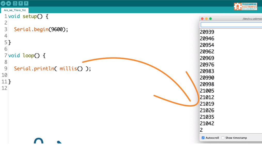
The easiest way to review this function is to look at it in a simple sketch. Let’s write a sketch that prints the value of millis to the serial monitor window.
In the Arduino IDE we’re going to begin in the setup section and use this Serial.begin function to enable serial communication.
Then in the loop we’re going to use the Serial.println (println = print line) function to print the value of millis.
void setup() {

  Serial.begin(9600);

}

void loop() {

  Serial.println( millis() );

}
Each time through the loop, this program will print the current value of the millis function. If we load this sketch onto our Arduino and open up the serial monitor window, you’ll see the value of millis is increasing rapidly.
So what is this value that the millis function returns?
The millis function returns the number of milliseconds that your Arduino board has been powered up.
In other words, when you upload your sketch to your Arduino, as soon as the upload is complete, the clock starts. Millis returns the number of milliseconds that have passed since this upload was completed.
Essentially, it’s a timer for how long the current program has been running. This is independent of the number of times the “void loop ()” has iterated.
So how high can it count up? It can count to 4,294,967,296… it would take 49 days to reach this number. Once it hits this number it “overflows”, which is just a fancy way of saying it then starts back over at zero and resumes counting up.
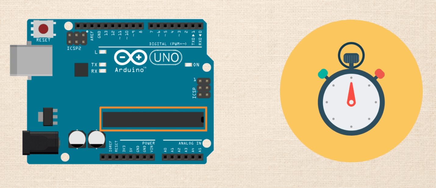
The way millis is able to track the number of milliseconds that have passed is by using the timer counter module that is built into the integrated circuit on the Arduino.
We don’t have to start the clock or start millis in our code, it starts all by itself in the background.
If you want to learn more about how the millis function works, definitely check out the first lesson in the series.
Example #2: Basic Delay with for() loops
For our 2nd example, we are only going to delay for 1ms, but do so inside of a for() loop.
void setup() {
   pinMode(13, OUTPUT);
}

void loop() {
   digitalWrite(13, HIGH);   // set the LED on
   for (int x=0; x < 1000; x++) {     // Wait for 1 second
      delay(1);
   }
   digitalWrite(13, LOW);   // set the LED on
   for (int x=0; x < 1000; x++) {     // Wait for 1 second
      delay(1);
   }
}
This new sketch will accomplish the same sequence as Example #1. The difference is that the Arduino is only “delayed” for one millisecond at a time. A clever trick would be to call other functions inside of that for() loop. However, your timing will be off because those instructions will add additional delay.
Millis timeline concept
To conceptualize millis so that we can use it to create timed repetitive events, let’s start by thinking of millis as moving along a timeline.
The timeline starts at zero and it goes all the way up to four billion and some change, and these numbers represent milliseconds.
So at any point during our program, we can call the millis function, and find out exactly where on the timeline we are.
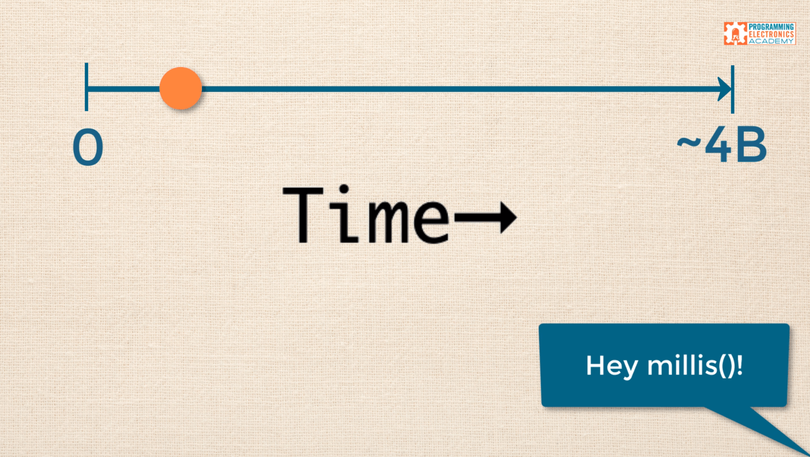
Let’s take a look at the first five seconds of a program. The little dot (in the picture below) represents where millis is on the timeline.
As soon as we power up Arduino, the millis function starts counting. You can see the value is increasing and moving to the right along the time axis. If we want to create timed repetitive events, how could we use this timeline to our advantage?
Example #1: Basic Delay
You are probably already familiar with this first code example The Arduino IDE includes this example as “Blink.”
void setup() {
   pinMode(13, OUTPUT);
}

void loop() {
   digitalWrite(13, HIGH);   // set the LED on
   delay(1000);              // wait for a second
   digitalWrite(13, LOW);    // set the LED off
   delay(1000);              // wait for a second
}
Reading each line of loop() in sequence the sketch:
- Turns on Pin 13’s LED,
- Waits 1 second (or 1000milliseconds),
- Turns off Pin 13’s LED and,
- Waits 1 second.
- Then the entire sequence repeats.
The potential issue is that while you are sitting at the delay(), your code can’t be doing anything else. So let’s look at an example where you aren’t “blocking” for that entire 1000 milliseconds.
Функция Millis ()
Как я уже упоминал, миллис-функция Arduino используется для измерения времени, и это делается в миллисекунды (мс), отсюда и его название. Другими словами, числовое значение, которое эта функция возвращает, когда вы включаете его в свой эскиз, является временными данными, выраженными в этой единице.
Вы должны знать, что максимальное значение этой переменной равно без знака долго, то есть долго без знака
Это важно, потому что при использовании меньшего размера могут возникнуть проблемы с логикой. Кроме того, вы должны знать, что он может длиться до 50 дней (4.320.000.000 XNUMX XNUMX XNUMX мс), как только он достигнет этого значения, он перезапустится и снова начнется с нуля
Еще вам нужно знать, что функция millis не использует параметры.
FAQ
Всё верно. Разработчики хотят иметь прибыль от своего полезного и качественного продукта.
Но для использования виртуальных пинов через вебхуки элементы управления не требуются, т.е. приложение можно использовать только для получения токена и бесплатно.
Можно только по Wi-Fi?
Нет. Подключение может любым: Wi-Fi, Ethernet, и даже COM-порт через USB компьютера. Всё зависит от целей, задач и вида микроконтроллера.
Почему не использовать готовые решения?
10. Именно такая цифра — делитель стоимости подобных «готовых» устройств (в некоторых случаях меньше или больше, но какой смысл переплачивать, если с равными усилиями получается дешевле и веселее?)
Что еще можно сделать по этой технологии?
А что угодно!
- Управляемую подсветку (меняющую цвет, яркость, режимы работы);
- Сбор информации с самых разных датчиков (температура, влажность, давление);
- Умные выключатели и розетки;
- ИК-пульт (наподобие Яндекс.Пульта);
- Управление компьютером через Алису;
- Голосовое управление детскими игрушками;
- Сигнализацию с постановкой на охрану голосом (и проверкой статуса).
А считывать состояния Blynk умеет?
Да, ссылка на запрос состояния выглядит так:
https://blynk-cloud.com/<ваш_токен>/get/V0
Так же можно считывать и состояния датчиков, но это тема уже совсем другой статьи 🙂
Насколько это надежно? (Китай долго не проработает…)
Ардуино (в том числе китайские версии) прошли в массах не одну проверку температурой, влажностью и временем. Лично на моем опыте собранные устройства функционируют по сей день в течение 3 лет. Что называется, слепил — и забыл.
Кроме того, модульные сборки имеют преимущество перед «коробочными» в том, что любой модуль, датчик, реле и т.п. можно заменить (при этом недорого!) без вреда для всей схемы. Их намного легче размещать в ограниченном пространстве (в кастомных корпусах, или вообще без корпуса).
А главный плюс — любое устройство в любой момент можно свободно развивать по функционалу в зависимости от приходящих в голову идей — бесценен!
Millis() Operation
At each interrupt of 1024us the millis() timer is incremented.
Since 1024us is greater than 1000us, the millis() timer is too slow and needs correcting.
The idea is to store the error and
accumulate it until it surpasses a threshold, upon which the
millisecond timer output is corrected.
So to correct to a 1ms output, The number of interrupts before a correction is needed is:
1000.0/24 = 41.66.
The above equation represents the number of 24us periods that add up
to 1ms i.e after 41.66 interrupts the error will be 1ms. Of course you
can’t get 41.66 interrupts so you have to wait for the following
interrupt to detect when the error is greater than 1000us. This will be
when 42 interrupts have occurred.
The clever part of the algorithm is that the error accumulator is
incremented by 24 every interrupt (the division is not performed — that
just lets you see the idea). When this variable is greater than 41.66*24
i.e 42*24 = 1008 then the error is corrected.
The next really, really, clever part of the algorithm is that the
error variable is not reset to zero — you just subtract the 1ms value
(since that was what was corrected) leaving the last value of the error
in the accumulator i.e. it will be 8 on this occasion. This error then
accumulates again and the millis() timer is again adjusted when the error is greater then 1ms.
From the analysis below the millis() timer will be
continuously corrected and is not in error by more than 2ms (See simulation and real output results below).
You can explore this further by looking at the code
that follows below. One thing to note is that the values are fitted into
bytes because they are all multiples of 8 (but this only works for 16MHz and 8MHz
clocks):
1024.0 / 8 = 128.0 ; 1024 >> 3 is exactly 128 i.e. fits in a byte.
1000.0 / 8 = 125.0 ; 1000 >> 3 is exactly 125 i.e. fits in a byte.
24.0 / 8 =
3.0 ; 24
>> 3 is exactly 3 i.e. fits in a byte.
These numbers are used in the code below.
2 things to avoid…
If you’re going to be doing math with an unsigned long, then ensure these two things:
First, any other variables that are going to be used to change that variable should also be an unsigned long.
Let’s say you’ve got a variable called previousTime and you’re going to subtract a value from it, and that value is in another variable, say it’s like currentTime. MAKE SURE that other variable, currentTime, is also a unsigned long.
if(currentTime - previousTime > 10000UL ){

  //Do this thing...
The second thing is if you’re going to be using any raw numbers to do a calculation on an unsigned long variable, make sure that at least one of the numbers in that calculation has a UL formatter at the end of it.
So for example, if you’re dividing previousTime, which is an unsigned long variable, by either 100 or 1000, then make sure that those numbers in the “denominator” are written as 100UL or 1000UL.
Raw numbers like these are called integer constants and if you don’t put that UL formatter on the end, then the calculation can create some really unexpected results.
We won’t get into the details about the strange results that can happen and necessarily why it happens, but basically it has to do with when those numbers roll over after they get to their maximum value.
The UL formatter at the end of that raw number tells the Arduino that it should be treated as an unsigned long.
This is the result you’ll get:
 Observe plus 1
 signed dec :1
 signed hex :1
 unsigned dec :1
 unsigned hex :1

 Observe minus 1
 signed dec :-1
 signed hex :FFFFFFFF
 unsigned dec :4294967295
 unsigned hex :FFFFFFFF

 suppose millis() reaches unsigned value 0xffffffff-1
 Observe the signed value
 signed dec :-2
 signed hex :FFFFFFFE
 unsigned dec :4294967294
 unsigned hex :FFFFFFFE

 Observe signed value of 0x7fffffff - no problem
 signed dec :2147483647
 signed hex :7FFFFFFF
 unsigned dec :2147483647
 unsigned hex :7FFFFFFF

 Observe signed value of 0x80000000 (The sign bit)
 signed dec :-2147483648
 signed hex :80000000
 unsigned dec :2147483648
 unsigned hex :80000000
You can see that the sign bit is very important (the left most bit) and if
you use signed types you will get negative output numbers displayed, even
though the unsigned version is correct i.e. it has the expected bit value — or
hex value shown.
Also shown is the flip over point where using signed long is OK until you
reach 2147483647 (0x7fffffff) add one to that and you get -2147483648
(0x80000000). In terms of days a timer will appear to work fine for ~ and then adding one results in a negative output.
The explanation of number of days that millis() covers is .
The easy way round that is to use unsigned long (uint32_t) when dealing with
millis().
Похожие записи:
 Как поставить сушильную машину, над стиральной?
 Пуэ-7 п.1.7.10-1.7.48 заземление и защитные меры электробезопасности область применения. термины и определения
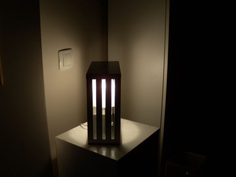 Светильник своими руками
 Как установить библиотеку eskw компас v16
 4 симулятора работы электрических схем на русском
 Почему при прохождении электрического тока проводник нагревается