Introduction
This Arduino code allows you to create a cheap 433MHz wireless transceiver to control electric switches and other home appliances. It can use USB or WiFi to connect to a computer to receive and send commands. It is mainly used for the homebridge-433-arduino plugin but can of course be used otherwise as well.
The project uses the PlatformIO IDE and runs on Arduino as well as ESP hardware. To decode signals the rc-switch or ESPiLight libraries can be used. Simple 433MHz receiver/sender hardware or more advanced CC1101 based transceiver modules are supported to send and receive 433MHz switch signals.
This is not meant to be an advanced firmware but a hobby software that is simple to use, build and understand.
Introduction
This plugin allows you to use cheap 433MHz wireless switches as lamps, fans or generic switches in HomeKit and control them using Siri. You can also use your 433Mhz remote to control things in HomeKit, like for example start scenes.
Improvements over other similar plugins
- Bidirectional, can send and receive switch signals
- Virtually no CPU load on the server (RasPi) even when receiving
- Sending signals works properly and sequentially, no broken signals when many devices are controlled
- Rock-solid RF signal quality and timing through external micro controller
- Transceiver can use WiFi so it doesn’t need a physical connection to the homebridge server
- Supports homebridge-config-ui-x to set up switches via web interface
Why use an external microcontroller?
There is plugins out there that use the Raspberry Pi GPIO functions to send and receive 433 MHZ data. The problem with these is that especially the receiving part requires quite a lot of CPU power as the RasPi lacks real hardware interrupts on its GPIO ports. Sending works okay most of the time if the RasPi isn’t under much load. The RasPi 1 can struggle to get accurate RF timing with short pulse durations even under low load however.
Additionally, the RasPi works on 3.3V and most simple 433MHz receivers/transmitters work best at 5V. The Arduino micro for example runs on 5V and allows a much more stable connection to the receivers and transmitters.
Supported switches
Most cheap 433 MHz switches should work, the transceiver can use either rc-switch or ESPiLight to encode and decode signals. ESPiLight is recommended as it supports more switch types but as the name suggests it requires ESP hardware.
Hardware Overview
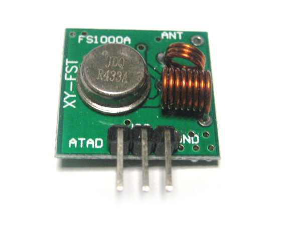
Let’s have a closer look at the 433MHz RF Transmitter and Receiver Modules.
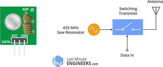
This little module is a transmitter among two. It is really simple as it looks. The heart of the module is the SAW resonator which is tuned for 433.xx MHz operation. There is a switching transistor and a few passive components, that’s it.
When a logic HIGH is applied to the DATA input, the oscillator runs producing a constant RF output carrier wave at 433.xx MHz and when the DATA input is taken to logic LOW, the oscillator stops. This technique is known as Amplitude Shift Keying, which we will discuss in detail shortly.
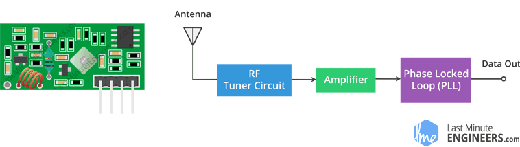
This one is a receiver module. Though it looks complex, it is as simple as the transmitter module. It consists of a RF tuned circuit and a couple of OP Amps to amplify the received carrier wave from the transmitter. The amplified signal is further fed to a PLL (Phase Lock Loop) which enables the decoder to “lock” onto a stream of digital bits which gives better decoded output and noise immunity.
Схема подключения передатчика и приемника 433 МГц к Arduino UNO
Теперь, когда мы знаем все о модулях, пришло время использовать их!
Поскольку мы будем передавать данные между двумя платами Arduino, нам, конечно, понадобятся две платы Arduino, две макетные платы и пара соединительных проводов.
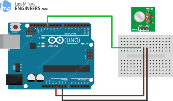
Схема для передатчика довольно проста. У него всего три соединения. Подключите контакт VCC к контакту 5 В и минус к Arduino. Контакт Data-In должен быть подключен к цифровому контакту Arduino № 12. Вы должны использовать контакт 12, так как по умолчанию библиотека, которую мы будем использовать в нашем скетче, использует этот контакт для ввода данных.
На следующем рисунке показана схема соединения.
После подключения передатчика вы можете перейти к приемнику. Подключение приемника так же просто, как и передатчика.
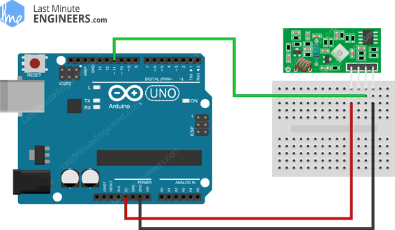
Так же нужно сделать только три соединения. Подключите контакт VCC к контакту 5 В и минус на Arduino. Любой из двух средних выводов Data-Out должен быть подключен к цифровому выводу № 11 на Arduino.
Вот так должна выглядеть схема соединения для приемника.
Теперь, когда передатчик и приемник подключены, нам нужно написать код и отправить его на соответствующие платы Arduino. Поскольку у вас, вероятно, только один компьютер, мы начнем с передатчика. Как только код будет загружен, мы перейдем к приемнику. Arduino, к которому подключен передатчик, может питаться от источника питания или батареи.
Исходный код программы (скетча)
Arduino
int f_button = 9;
int b_button = 8;
int l_button = 7;
int r_button = 6;
int m1 = 2;
int m2 = 3;
int m3 = 4;
int m4 = 5;
void setup () {
pinMode(f_button, INPUT_PULLUP);
pinMode(b_button, INPUT_PULLUP);
pinMode(l_button, INPUT_PULLUP);
pinMode(r_button, INPUT_PULLUP);
pinMode(m1, OUTPUT);
pinMode(m2, OUTPUT);
pinMode(m3, OUTPUT);
pinMode(m4, OUTPUT);
}
void loop() {
if ( digitalRead(f_button) == LOW)
{
digitalWrite(m1, LOW);
digitalWrite(m3, LOW);
digitalWrite(m2, HIGH );
digitalWrite(m4, HIGH);
}
if ( digitalRead(b_button) == LOW)
{
digitalWrite(m2, LOW);
digitalWrite(m4, LOW);
digitalWrite(m1, HIGH);
digitalWrite(m3, HIGH);
}
if ( digitalRead(l_button) == LOW)
{
digitalWrite(m1, LOW);
digitalWrite(m2, HIGH);
digitalWrite(m3, HIGH);
digitalWrite(m4, HIGH);
}
if ( digitalRead(r_button) == LOW)
{
digitalWrite(m1, HIGH);
digitalWrite(m2, LOW);
digitalWrite(m3, HIGH);
digitalWrite(m4, HIGH);
}
}
|
1 |
intf_button=9; intb_button=8; intl_button=7; intr_button=6; intm1=2; intm2=3; intm3=4; intm4=5; voidsetup(){ pinMode(f_button,INPUT_PULLUP); pinMode(b_button,INPUT_PULLUP); pinMode(l_button,INPUT_PULLUP); pinMode(r_button,INPUT_PULLUP); pinMode(m1,OUTPUT); pinMode(m2,OUTPUT); pinMode(m3,OUTPUT); pinMode(m4,OUTPUT); } voidloop(){ if(digitalRead(f_button)==LOW) { digitalWrite(m1,LOW); digitalWrite(m3,LOW); digitalWrite(m2,HIGH); digitalWrite(m4,HIGH); } if(digitalRead(b_button)==LOW) { digitalWrite(m2,LOW); digitalWrite(m4,LOW); digitalWrite(m1,HIGH); digitalWrite(m3,HIGH); } if(digitalRead(l_button)==LOW) { digitalWrite(m1,LOW); digitalWrite(m2,HIGH); digitalWrite(m3,HIGH); digitalWrite(m4,HIGH); } if(digitalRead(r_button)==LOW) { digitalWrite(m1,HIGH); digitalWrite(m2,LOW); digitalWrite(m3,HIGH); digitalWrite(m4,HIGH); } } |
Объяснение программы для Raspberry Pi
Полный код программы приведен в конце статьи, здесь же мы кратко рассмотрим его основные фрагменты.
Программировать плату Raspberry Pi в нашем проекте мы будем с использованием языка Python3. Также можно использовать и язык C/C++ как и в плате Arduino, однако в данном случае преимуществом написания программы на языке python является то, что на нем написана специальная библиотека для работы с модулями nRF24l01, которую можно скачать с ее официальной страницы на github. Но здесь необходимо отметить, что наша программа на python и указанная библиотека должны находиться в одном и том же каталоге, иначе программа на python не сможет найти библиотеку. После скачивания библиотеки извлеките ее из архива и создайте отдельный каталог, в котором будут храниться все программы и библиотеки вашего проекта. Когда установка библиотеки будет закончена, можно приступать к написанию программы.
Первым делом в программе необходимо подключить (импортировать) все используемые библиотеки.
Python
import RPi.GPIO as GPIO
import time
import spidev
from lib_nrf24 import NRF24
|
1 |
importRPi.GPIO asGPIO importtime importspidev fromlib_nrf24 importNRF24 |
Далее установим режим работы контактов (GPIO mode) платы Raspberry Pi «Broadcom SOC channel», что будет означать что мы будем обращаться к контактам платы по их физическим номерам (а не по их номерам на плате).
Python
GPIO.setmode(GPIO.BCM)
| 1 | GPIO.setmode(GPIO.BCM) |
Далее в программе мы зададим адреса каналов (pipe address) – они будут нужны для взаимодействия с приемной частью проекта на основе платы Arduino. Адреса укажем в шестнадцатеричном коде.
Python
pipes = , ]
| 1 | pipes=0xE0,0xE0,0xF1,0xF1,0xE0,0xF1,0xF1,0xF0,0xF0,0xE0 |
Инициализируем модуль nRF24l01 используя контакты GPIO08 в качестве CE и GPIO25 в качестве CSN.
Python
radio.begin(0, 25)
| 1 | radio.begin(,25) |
Установим размер пакета (payload size) 32 бита, адрес канала 76, скорость передачи данных 1 Мбит/с и выходную мощность модуля на минимум.
Python
radio.setPayloadSize(32)
radio.setChannel(0x76)
radio.setDataRate(NRF24.BR_1MBPS)
radio.setPALevel(NRF24.PA_MIN)
|
1 |
radio.setPayloadSize(32) radio.setChannel(0x76) radio.setDataRate(NRF24.BR_1MBPS) radio.setPALevel(NRF24.PA_MIN) |
Откроем каналы и начнем в них запись данных. Также будем выводить на экран основные параметры (details) работы модуля nRF24l01.
Python
radio.openWritingPipe(pipes)
radio.printDetails()
|
1 |
radio.openWritingPipe(pipes) radio.printDetails() |
Подготовим сообщение в форме строки. Это сообщение мы будем передавать плате Arduino UNO.
Python
sendMessage = list(«Hi..Arduino UNO»)
while len(sendMessage) < 32:
sendMessage.append(0)
|
1 |
sendMessage=list(«Hi..Arduino UNO») whilelen(sendMessage)<32 sendMessage.append() |
Начнем запись информации в радио модуль и будем продолжать запись пока не закончится вся строка для передачи. Одновременно с этим зафиксируем текущее время и выведем на экран сообщение об успешной передаче (в целях отладки).
Python
while True:
start = time.time()
radio.write(sendMessage)
print(«Sent the message: {}».format(sendMessage))
send
radio.startListening()
|
1 |
whileTrue start=time.time() radio.write(sendMessage) print(«Sent the message: {}».format(sendMessage)) send radio.startListening() |
Если передача сообщения завершена и радио канал закрыт (не доступен) более 2-х секунд, то выведем на экран сообщение о том, что время истекло (timed out).
Python
while not radio.available(0):
time.sleep(1/100)
if time.time() — start > 2:
print(«Timed out.») # print error message if radio disconnected or not functioning anymore
break
|
1 |
whilenotradio.available() time.sleep(1100) iftime.time()-start>2 print(«Timed out.»)# print error message if radio disconnected or not functioning anymore break |
Закрываем прослушивание (listening) радио канала, закрываем соединение и заново открываем соединение спустя 3 секунды чтобы передать другое сообщение.
Python
radio.stopListening() # close radio
time.sleep(3) # give delay of 3 seconds
|
1 |
radio.stopListening()# close radio time.sleep(3)# give delay of 3 seconds |
Двигатели и пропеллеры для лодки
Здесь также необходимо учитывать вес компонентов, поэтому в качестве двигателей мы выбрали электродвигатели постоянного тока типа n20, работающие от 5 В и отличающиеся малыми размерами и массой. Для предотвращения появления радиопомех необходимо подключить конденсатор 0,1 мкФ параллельно входным контактам двигателя.
Пропеллеры (воздушные винты) для лодки мы изготовили из листов пластмассы, но при желании их можно купить в соответствующих магазинах. Мы же просто вырезали из пластика необходимые полоски, согнули их при помощи нагрева от свечи и проделали в них небольшой отверстие чтобы закрепить их на осях двигателей.
Arduino with RF 433MHz Transmitter/Receiver Modules
In this section, we’ll build a simple example that sends a message from an Arduino to another Arduino board using 433 MHz. An Arduino board will be connected to a 433 MHz transmitter and will send the “Hello World!” message. The other Arduino board will be connected to a 433 MHz receiver to receive the messages.
Parts Required
You need the following components for this example:
- 2x Arduino – read Best Arduino Starter Kits
- RF 433MHz Receiver/Transmitter
- Breadboard
- Jumper wires
You can use the preceding links or go directly to MakerAdvisor.com/tools to find all the parts for your projects at the best price!
Installing the RadioHead Library
The RadioHead library provides an easy way to work with the 433 MHz transmitter/receiver with the Arduino. Follow the next steps to install that library in the Arduino IDE:
- Click here to download the RadioHead library. You should have a .zip folder in your Downloads folder.
- Unzip the RadioHead library.
- Move the RadioHead library folder to the Arduino IDE installation libraries folder.
- Restart your Arduino IDE
The RadioHead library is great and it works with almost all RF modules in the market. You can read more about the RadioHead library here.
Transmitter Circuit
Wire the transmitter module to the Arduino by following the next schematic diagram.
Important: always check the pinout for the transmitter module you’re using. Usually, there are labels next to the pins. Alternatively, you can also take a look at your module’s datasheet.
Transmitter Sketch
Upload the following code to the Arduino board that will act as a transmitter.
How the transmitter sketch works
First, include the RadioHead ASK library.
This library needs the SPI library to work. So, you also need to include the SPI library.
After that, create a RH_ASK object called driver.
In the setup(), initialize the RH_ASK object by using the init() method.
In the loop(), we write and send our message. The message is saved on the msg variable. Please note that the message needs to be of type char.
This message contains the “Hello World!” message, but you can send anything you want as long as it is in char format.
Finally, we send our message as follows:
The message is being sent every second, but you can adjust this delay time.
Receiver Circuit
Wire the receiver module to another Arduino by following the next schematic diagram.
Important: always check the pinout for the transmitter module you’re using. Usually, there are labels next to the pins. Alternatively, you can also take a look at your module’s datasheet.
Receiver Sketch
Upload the code below to the Arduino connected to the receiver.
How the receiver sketch works
Similarly to the previous sketch, you start by including the necessary libraries:
You create a RH_ASK object called driver:
In the setup(), initialize the RH_ASKobject.
In the loop(), we need to set a buffer that matches the size of the message we’ll receive. “Hello World!” has 12 characters. You should adjust the buffer size accordingly to the message you’ll receive (spaces and punctuation also count).
Then, check if you’ve received a valid message. If you receive a valid message, print it in the serial monitor.
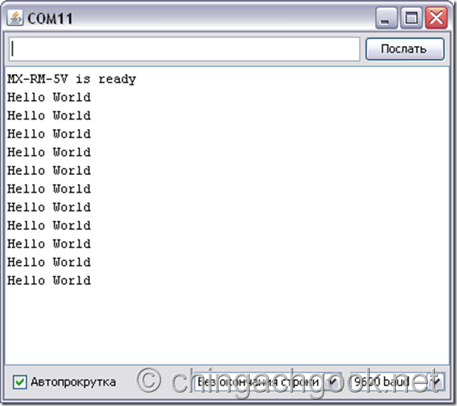
Demonstration
In this project the transmitter is sending a message “Hello World!” to the receiver via RF. Those messages are being displayed in receiver’s serial monitor. The following figure shows what you should see in your Arduino IDE serial monitor.
Примеры кода для работы с передатчиком MX-F01 с использованием библиотеки VirtualWire
Пример 1
Данный скетч будет отправлять раз в секунду сообщение «Hello World». Для наглядности, в начале передачи будет загораться светодиод, а после окончания – гаснуть.
const int led_pin = 13; // Пин светодиода const int transmit_pin = 12; // Пин подключения передатчика
void setup() vw_set_tx_pin(transmit_pin); vw_setup(2000); // Скорость передачи (Бит в секунду) pinMode(led_pin, OUTPUT); >
void loop() const char *msg = «Hello World»; // Передаваемое сообщение digitalWrite(led_pin, HIGH); // Зажигаем светодиод в начале передачи vw_send((uint8_t *)msg, strlen(msg)); // Отправка сообщения vw_wait_tx(); // Ожидаем окончания отправки сообщения digitalWrite(led_pin, LOW); // Гасим светодиод в конце передачи delay(1000); // Пауза 1 секунда >
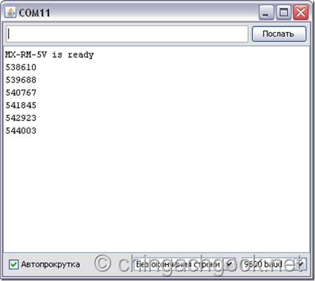
Пример 2
Данный скетч будет отправлять раз в секунду сообщение, которое содержит количество миллисекунд, прошедшее с момента начала выполнения текущей программы. Для наглядности, в начале передачи будет загораться светодиод, а после окончания – гаснуть.
const int led_pin = 13; // Пин светодиода const int transmit_pin = 12; // Пин подключения передатчика
void setup() vw_set_tx_pin(transmit_pin); vw_setup(2000); // Скорость передачи (Бит в секунду) pinMode(led_pin, OUTPUT); >
void loop() digitalWrite(led_pin, HIGH); // Зажигаем светодиод в начале передачи
String millisresult = String(millis()); // Присваиваем переменной значение, равное количеству миллисекунд с момента начала выполнения текущей программы char msg; millisresult.toCharArray(msg, 14);
vw_send((uint8_t *)msg, strlen(msg)); // Отправка сообщения vw_wait_tx(); // Ожидаем окончания отправки сообщения digitalWrite(led_pin, LOW); // Гасим светодиод в конце передачи delay(1000); // Пауза 1 секунда >
Пример кода для работы с приемником MX-RM-5V с использованием библиотеки VirtualWire
byte message; // Буфер для хранения принимаемых данных byte messageLength = VW_MAX_MESSAGE_LEN; // Размер сообщения
const int led_pin = 13; // Пин светодиода const int receiver_pin = 12; // Пин подключения приемника
void setup() Serial.begin(9600); // Скорость передачиданных Serial.println(«MX-RM-5V is ready»); vw_set_rx_pin(receiver_pin); // Пин подключения приемника
vw_setup(2000); // Скорость передачи данных (бит в секунду) vw_rx_start(); // Активация применика > void loop() if (vw_get_message(message, &messageLength)) // Если есть данные.. digitalWrite(led_pin, HIGH); // Зажигаем светодиод в начале приема пакета for (int i = 0; i
Для “Пример 2” кода передатчика
Не забудьте припаять антенны, а то без них дальность передачи будет всего несколько сантиметров.
Частота 433.920 МГц выделена для работы маломощных цифровых передатчиков таких как: радиобрелки автосигнализаций, брелки управления шлагбаумами на стоянках и другие подобные системы.
Источник
RadioHead Library — универсальная библиотека для беспроводных модулей
Прежде чем мы начнем программировать, установим библиотеку RadioHead в Arduino IDE.
RadioHead — это библиотека, которая позволяет легко передавать данные между платами Arduino. Она настолько универсальна, что ее можно использовать для управления всеми видами устройств радиосвязи, включая наши модули на 433 МГц.
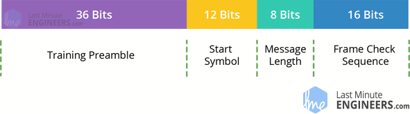
Библиотека RadioHead собирает наши данные, инкапсулирует их в пакет данных, который включает в себя CRC (проверку циклически избыточного кода), а затем отправляет его с необходимой преамбулой и заголовком на другую Arduino. Если данные получены правильно, принимающая плата Arduino проинформирует о наличии доступных данных и приступит к их декодированию и выполнению.
Пакет RadioHead формируется следующим образом: 36-битный поток из пар «1» и «0», называемый «обучающей преамбулой», отправляется в начале каждой передачи. Эти биты необходимы приемнику для регулировки его усиления до получения фактических данных. Затем следует 12-битный «Начальный символ», а затем фактические данные (полезная нагрузка).
Последовательность проверки или CRC добавляется в конец пакета, который пересчитывается RadioHead на стороне приемника, и если проверка CRC верна, приемное устройство получает предупреждение. Если проверка CRC не пройдена, пакет отбрасывается.
Весь пакет выглядит примерно так:
Description
Throughout this tutorial we’ll be using the FS1000A transmitter and corresponding receiver, but the instructions provided also work with other 433MHz transmitter/receiver modules that work in a similar fashion. These RF modules are very popular among the Arduino tinkerers and are used on a wide variety of applications that require wireless control.
These modules are very cheap and you can use them with any microcontroller, whether it’s an Arduino, ESP8266, or ESP32.
Specifications RF 433MHz Receiver
- Frequency Range: 433.92 MHz
- Modulation: ASK
- Input Voltage: 5V
- Price: $1 to $2
Specifications RF 433MHz Transmitter
- Frequency Range: 433.92MHz
- Input Voltage: 3-12V
- Price: $1 to $2
Where to buy?
You can purchase these modules for just a few dollars. Click here to compare the RF 433MHz transmitter/receiver on several stores and find the best price.
RadioHead Library – a Swiss Army Knife for wireless modules
Before we start coding, there is a library called RadioHead we will need to install into our Arduino IDE that will make writing the code a lot simpler.
RadioHead is a library that allows simple data transfer between Arduino boards. It’s so versatile that it can be used to drive all sorts of radio communications devices, including our 433MHz modules.
What RadioHead library does is to take our data, encapsulate it into a packet of data which includes a CRC (Cyclic Redundancy Check) and then send it with the necessary preamble and header to another Arduino. If the data is received correctly, the receiving Arduino is informed that there is data available and proceeds to decode and action it.
The RadioHead Packet is made up as follows: A 36 bit stream of “1” and “0” bit pairs, called a “Training Preamble”, is sent at the start of every transmission. These bits are necessary for the receiver to adjust its gain prior to getting the actual data. Followed by this, a 12 bit “Start Symbol” and then the actual data (payload) is added.
A Frame Check Sequence or CRC is added at the end of the packet which is recalculated by RadioHead at the receiver end and if the CRC check is correct, the receiving device is alerted. If the CRC check fails, the packet is discarded.
The whole packet looks something like this:
You can download the library, by visiting the airspayce.com or, just click this button to download the zip:
To install it, open the Arduino IDE, go to Sketch > Include Library > Add .ZIP Library, and then select the RadioHead file that you just downloaded. If you need more details on installing a library, visit this Installing an Arduino Library tutorial.
Wiring – Connecting 433MHz RF Transmitter and Receiver to Arduino UNO
Now that we know everything about the modules it is time to put them to use!
As we will be sending data between two Arduino boards, we will of course need two Arduino boards, two breadboards and a couple of jumper wires.
The wiring for the transmitter is fairly simple. It has only three connections. Connect the VCC pin to 5V pin and GND to ground on the Arduino. The Data-In pin should be connected to Arduino’s digital pin #12. You should try and use pin 12 as by default the library we’ll be using in our sketch uses this pin for data input.
The following illustration shows the wiring.
Once you have the transmitter wired you can move on to the receiver. The wiring for the receiver is just as easy as the transmitter was.
Once again there are only three connections to make. Connect the VCC pin to 5V pin and GND to ground on the Arduino. Any of the middle two Data-Out pins should be connected to digital pin #11 on the Arduino.
This is how wiring for the receiver should look like.
Now that both the transmitter and receiver are wired up we will need to write some code and send it to the respective Arduino boards. Since you probably have only one PC, we will start with the transmitter. Once the code has been loaded there, we’ll move on to the receiver. The Arduino to which transmitter is connected can then be powered using a power supply or battery.
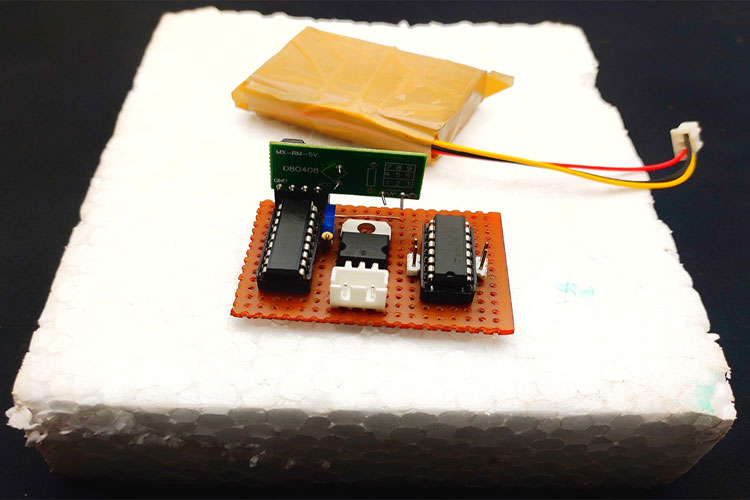
Сборка корпуса приемной части проекта
Мы пробовали различные материалы для изготовления корпуса лодки, но наилучших результатов мы достигли с помощью листа такого материала как thermocol (его можно купить, но почему то точного перевода этого слова я не нашел). Мы взяли лист толщиной 3 см из этого материала и положили сверху на него печатную плату приемной части нашего проекта. После этого мы обозначили контуры необходимо углубления для размещения электронной части и вырезали его в листе thermocol’а. Разумеется, вы можете изготовить корпус лодки исходя из собственных предпочтений, можно для этих целей также использовать игрушечную лодку.
Радио передатчик XD-RF-5V 433Mhz
Характеристики XD-RF-5V
Рабочее напряжение: 3V ~ 12VРабочий ток: 20 мА ~ 28mAРезервное течение: 0mAРабочая частота: 433MHzРасстояние передатчика: >500 м (чувствительность может быть выше-103dBm если в широком поле)Выходная мощность: 16dBm (40 мВт)Скорость Передатчик: Режим модуляции: ООК (AM)Рабочая температура: -10 ° C ~ +70 ° CРазмер: 19 х 19 х 8 мм
Для подключения имеет выводы PIN1 DATA, PIN2 VCC, PIN3 GND. Встроенной антенны нет, но есть контакт для ее подключения. Зачастую для увеличения дальности передачи изготоваливают проволочные антенны.Передатчик применяется в устройствах умного дома, автоматических системах сбора данных. Главным преимуществом является неприхотливость, стабильность в работе и низкое энергопотребление. Из минусов стоит отметить его «аналоговость». Нужно усложнять программный код для кодирования потока данных, но это же и является преимуществом т.к. нет никаких ограничений на протокол связи.
Скетч Arduino для радиочастотного передатчика 433 МГц
В нашем эксперименте мы отправим простое текстовое сообщение от передатчика к получателю. Будет полезно понять, как использовать модули, и это может послужить основой для более практических экспериментов и проектов.
Вот скетч, который мы будем использовать для нашего передатчика:
// Подключаем библиотеку RadioHead Amplitude Shift Keying
#include <RH_ASK.h>
// Подключаем библиотеку SPI Library
#include <SPI.h>

// Создаем объект управления смещением амплитуды
RH_ASK rf_driver;

void setup()
{
    // Инициализируем объект ASK
    rf_driver.init();
}

void loop()
{
    const char *msg = "Hello World";
    rf_driver.send((uint8_t *)msg, strlen(msg));
    rf_driver.waitPacketSent();
    delay(1000);
}
Это довольно короткий набросок, но это все, что вам нужно для передачи сигнала.
Код начинается с подключения библиотеки RadioHead ASK. Мы также должны подключить библиотеку SPI Arduino, так как от нее зависит библиотека RadioHead.
#include <RH_ASK.h>
#include <SPI.h>
Далее нам нужно создать объект ASK, чтобы получить доступ к специальным функциям, связанным с библиотекой RadioHead ASK.
// Создаем объект управления смещением амплитуды
RH_ASK rf_driver;
В функции setup() нам нужно инициализировать объект ASK.
// Инициализируем объект ASK
    rf_driver.init();
В функции loop() мы начинаем с подготовки сообщения. Это простая текстовая строка, которая хранится в char с именем msg. Знайте, что ваше сообщение может быть любым, но не должно превышать 27 символов для лучшей производительности. И обязательно посчитайте количество символов в нем, так как вам понадобится это количество в коде получателя. В нашем случае у нас 11 символов.
// Готовим сообщение
const char *msg = "Hello World";
Затем сообщение передается с использованием функции send(). Он имеет два параметра: первый — это массив данных, а второй — количество байтов (длина данных), подлежащих отправке. За send() функцией обычно следует waitPacketSent() функция, которая ожидает завершения передачи любого предыдущего передаваемого пакета. После этого код ждет секунду, чтобы дать нашему приемнику время разобраться во всем.
rf_driver.send((uint8_t *)msg, strlen(msg));
rf_driver.waitPacketSent();
delay(1000);
Что такое LoRa?
Термин LoRa означает Long Range. Это беспроводная технология радиочастот, представленная компанией Semtech. Технология LoRa может использоваться для передачи двунаправленной информации на большие расстояния без больших затрат энергии. Это свойство может использоваться удаленными датчиками, которые должны передавать свои данные, просто работая на одном заряде небольшой батареи.
Сигналы LoRa при определенных условиях могут преодолевать расстояние 15-20 км и работать от батареи в течение многих лет. Помните, что LoRa, LoRaWAN и LPWAN – это три разных термина, и их не следует путать друг с другом.
Похожие записи:
 Лучшие ибп для дома
 Ветроэнергетика
 Описание, технические характеристики и аналоги выпрямительных диодов серии 1n4001-1n4007
 Делаем проводку в гараже своими руками: схема подключения, электрощиток, заземление и фото
 Простой самодельный усилитель мощности нч на пяти транзисторах 100-200 ватт (tip142, tip147)
 Люминесцентные лампы характеристики