Rotate the screen #
You can change the screen position and the origin of the with the node.
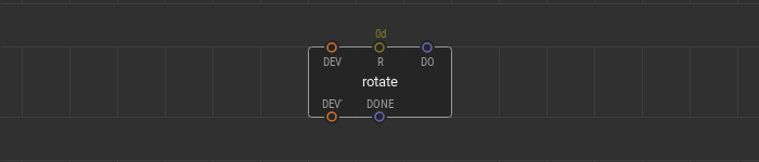
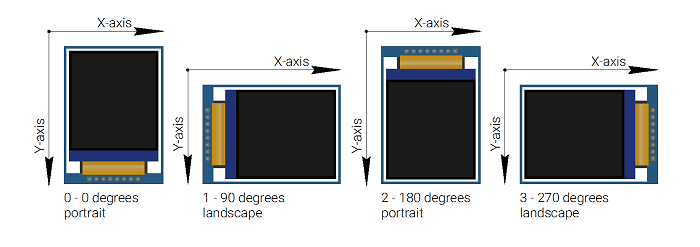
The node allows you to rotate the display screen to one of four positions: 0 degrees portrait, 90 degrees landscape, 180 degrees portrait, and 270 degrees landscape. A value at the pin sets the angle to rotate the screen and can be one of four values , , , . These values correspond to the particular display positions.
A type signal at the pin triggers a new screen rotation and the coordinate system change. The pulse at the output pin signals that the rotation is complete. The can be used in run-time and at any step of the program. It is possible to use several nodes.
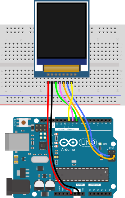
Connecting TFT display to Arduino.
This is the type of display am using but they come with various pin configurations. However all the displays will have the major pins stated below and should be connected to the Arduino board as follows:SCK to Digital pin 13SDA to Digital pin 11DC to Digital pin 9Reset to Digital pin 8CS to Digital pin 10GND to Arduino GNDVCC to Arduino 3.3V
This TFT display uses 3.3V but comes with an on board voltage regulator therefore the VCC can be connected to the Arduino 5V. However for best practice it’s better to use the 3.3V.
Most code Libraries for this TFT ST7735 display with Arduino are programmed with the SDA and SCL pins connected to Arduino pins 11 and 13 respectively. Make sure you don’t change that order otherwise the display may not work.
Quick start example #
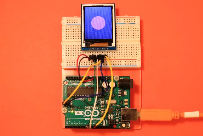
Here is a simple example of using quickstart nodes. For example, We use an ST7735 128×160 SPI display of a “G” type. Connect it to a microcontroller according to the wiring scheme.
Use the hardware SPI bus. Connect the display’s pin to the controller port, and the pin to the port. The breakout board of the display used in this example has an pin, so it should be wired. The pin is connected to the port.
Let’s display a pink filled circle in the center of the screen.
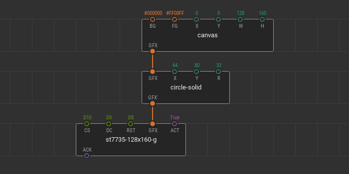
Put the quickstart node onto the patch and fill in ports values , , and according to the wiring scheme. Using the XOD graphics library, create a new with the size of a display screen. The width of the is and the height is . The background color is set to black () and the foreground color to pink ().
To add the filled circle to the scene, place the node onto the patch. To make this node be a part of the graphic tree, link its pin with the pin of the . Set the circle coordinates for the center of the screen, for , and for . The radius can be random, for example, .
The scene is ready. Connect the output pin of the node to the pin of the quickstart node. Take a look at what the patch should be.
Upload this patch and see what is displayed on the screen of the device.
You can change all parameters of the graphic nodes in a real-time. For example, you can change the position of the circle or the background color of the canvas using tweaks. Add two nodes for the and circle coordinates. Add the node for the pin. Flash the patch in debug mode and manage colors and coordinates.
The parameters of graphic nodes can be changed using other nodes. For example, you can change the color of the circle and its size using a potentiometer. Remove tweak nodes from the patch. Place new nodes , , and node from the library. Connect the potentiometer to the Arduino port.
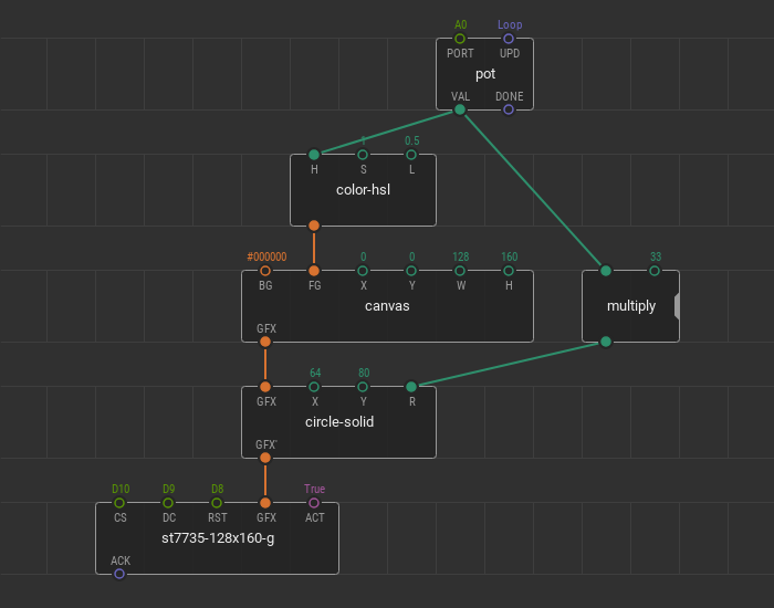
With the combination of and , the radius of the circle changes from to pixels. With the combination of and , the hue of the foreground color of the canvas changes from to . Upload the patch and manage the graphics changes.
Code for running the ST7735 TFT Display.
There are a number of libraries that have been developed to run the TFT ST7735 color display using Arduino but I found the Adafruit-ST7735-Library the best to use. Make sure you have this library installed in your IDE.
Basic commands.
Most TFT libraries have been programmed to support the following commands:
- This function is for changing the color of the screen.
- For setting the cursor position using x and y coordinates of the screen.
- For setting the color of text.
- Setting the color of text and its background.
- For setting the size of text. This should be from 1 to 5.
- Rotating the screen. Can take values of 0 for 0 degrees, 1 for 90 degrees, 2 for 180 degrees and 3 for 270 degrees.
- For displaying a string.
- Displaying a string and moves the cursor to the next line.
- This function draws a vertical line that starts in x, y location, and its length is h pixel and its color is t.
- This function draws a horizontal line that starts in x, y location, and its length is w pixel and its color is t.
- This function draws a line that starts in xi and yi location ends is in xj and yj and the color is t.
- function draws a rectangle in x and y location with w width and h height and t color.
- function draws a filled rectangle in x and y location. w is width, h is height and t is color of the rectangle
- function draws a circle in x and y location and r radius and t color.
- function draws a filled circle in x and y location and r radius and t color.
- function draws a triangle with three corner location x, y and z, and t color.
- function draws a filled triangle with three corner location x, y and z, and t color.
- function draws a Rectangle with r radius round corners in x and y location and w width and h height and t color.
- function draws a filled Rectangle with r radius round corners in x and y location and w width and h height and t color.
There are many other functions and commands which you can use to program the TFT color display but the above are the commonest. You will meet many more with practice.
Before we can write our personal code we need to first test the display using the already made code examples from the installed library. This is done by going to File>Examples>Adafruit ST7735 and ST7789 Library. Then you can select any of the examples and upload it to the setup to see if the display works fine.In the diagram below I have shown how to access the graphics test code.
The example below shows the basic use of the above commands and functions for displaying simple colored shapes, lines and words on the TFT display.
#include <SPI.h>
#include <Adafruit_GFX.h>    // Core graphics library
#include <Adafruit_ST7735.h> // Hardware-specific library

#define TFT_CS        10
#define TFT_RST        7 // Or set to -1 and connect to Arduino RESET pin
#define TFT_DC         9

Adafruit_ST7735 tft = Adafruit_ST7735(TFT_CS, TFT_DC, TFT_RST);

void setup(void) {
  tft.initR(INITR_144GREENTAB); // Init ST7735R chip, green tab
  //tft.fillScreen(ST77XX_BLACK);
  tft.setRotation(0); // set display orientation
}

void loop() {
  tft.fillScreen(ST77XX_CYAN);
  print_text(25,30,"HELLO",3,ST77XX_ORANGE);
  print_text(20,70,"WORLD!",3,ST77XX_BLUE);
  delay(5000);

  tft.fillScreen(ST77XX_BLACK);
  tft.fillRoundRect(25, 10, 78, 60, 8, ST77XX_WHITE);
  tft.fillTriangle(42, 20, 42, 60, 90, 40, ST77XX_RED);
  delay(5000);

  tft.fillScreen(ST77XX_CYAN);
  tft.drawRect(5,5,120,120,ST77XX_RED);
  tft.drawFastHLine(5,60,120,ST77XX_RED);
  tft.drawFastVLine(60,5,120,ST77XX_RED);
  delay(5000);
}

void print_text(byte x_pos, byte y_pos, char *text, byte text_size, uint16_t color) {
  tft.setCursor(x_pos, y_pos);
  tft.setTextSize(text_size);
  tft.setTextColor(color);
  tft.setTextWrap(true);
  tft.print(text);
}
Please also check out these other projects to better understand how the ST7735 TFT display is used with Arduino;
Displaying Images from Micro SD card on ST7735 Display using Arduino.
Simple Ultrasonic Radar.
Weather Station using BME280 Temperature and humidity sensor and Arduino.
report this ad
Техническое описание
Функции контроллера контактного интерфейса
| Pin | Символы | I/O | Функции |
|---|---|---|---|
| 1 | VLED- | P | Back light cathode |
| 2 | VLED | P | Back light anode |
| 3 | IM0 | I | — MCU Parallel Interface Type Selection -If Not Used, Please Fix this Pin at VDDI or DGND Level. 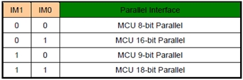 |
| 4 | IM1 | ||
| 5 | IM2 | I | MCU Parallel Interface Bus and Serial Interface select IM2=’1′, Parallel Interface IM2=’0′, Serial Interface |
| 6 | RESET | P | Reset signal |
| 7-12 | NC | — | No Connect |
| 13-28 | DB15-DB0(SPI_SDA) | I/O | DB15:0] are used as MCU parallel interface data bus. -DBis the serial input/output signal in serial interface mode. -In serial interface, DB15:1] are not used and should be fixed at VDDI or DGND level. |
| 29 | NC | — | No Connect |
| 30 | RD | I | Read Enable in 8080 MCU Parallel Interface. -If not used, please fix this pin at VDDI or DGND level. |
| 31 | WR | I | Serial clock -Write Enable in MCU Parallel Interface. -If not used, please fix this pin at VDDI or DGND level. |
| 32 | D/C(SPI_SCL) | I | -Display data/command Selection Pin in MCU Interface. -D/CX=’1′: Display Data or Parameter. -D/CX=’0′: Command Data. -In Serial Interface, this is used as SCL. -If not used, please fix this pin at VDDI or DGND level. |
| 33 | CS(SPI_CS) | I | Chip enable |
| 34 | IOVCC | P | Interface Operation Voltage |
| 35 | VCI | P | Analog Supply Voltage |
| 36 | GND | P | Ground |
| 37-40 | NC | — | No Connect |
Основные характеристики
| Наименование | Измерения | Единица |
|---|---|---|
| Диагональ | 1.77 | дюйма |
| Разрешение | 128 × RGB × 160(TFT) | точек |
| Габариты | 34.0(W) × 45.83(H) × 2.65(D) | mm |
| Активная область | 28.03 × 35.04 | mm |
| Шаг пикселя | 0.073 × 0.219 | mm |
| LCD Тип | TFT, Белый, Трансмиссивный | |
| Угол обзора | на 6 часов | |
| Инверсия | на 12 часов | |
| Соотношение сторон | портретный режим | |
| IC | ST7735S | |
| Тип подсветки | LED, Белый | |
| Сенсорный экран | Без сенсорной панели | |
| Поверхность | Антибликовая |
Абсолютные максимальные значения
| Наименование | Символы | Минимальный | Типичный | Максимальный | Единица |
|---|---|---|---|---|---|
| Диапазон рабочих температур | TOP | -20 | - | 70 | ℃ |
| Температура хранения | TST | -30 | - | 80 | ℃ |
Электронные характеристики
| Наименование | Символы | Кондиция | Минимальный | Типичный | Максимальный | Единица |
|---|---|---|---|---|---|---|
| Supply Voltage For Analog | VCI | - | 2.5 | 2.75 | 4.8 | V |
| Interface Operation Voltage | IOVCC | - | 1.65 | 1.8 | 3.7 | V |
| Supply LCM current | ICI(mA) | - | - | 0.9 | 2 | mA |
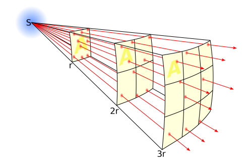
Render the scene #
The node is your main tool to display . The processes a single branch of the graphic tree created using the graphics library, renders it, and displays at the device.
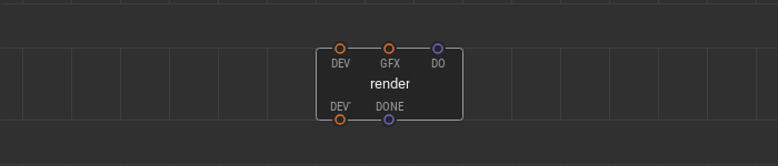
A graphic tree branch to render links to the input pin. A pulse signal at the pin is a trigger to process the graphic scene and display it. If the scene is rendered, a pulse comes to the output pin.
Use multiple nodes simultaneously. Processing various branches of the graphic tree at a different time, you can show dynamic graphic scenes at the screen.
Here is the example of a three nodes use. The tree of graphic elements consists of a and two on it. The device node and three nodes are linked together in a daisy chain. All nodes have different triggering algorithms at their pins.
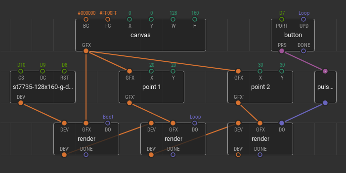
The first is on ; it fills the display screen with a specified only once — after powering the device. The second is responsible for on the canvas. Its trigger is set to . It means that any changes in the position are immediately shown on the screen. The third is responsible for displaying the and its trigger is linked to the . Here you can also change the position, but the changes are displayed only after the button click.
Описание
WF18FTLAADNN0 – это 1.77” дюймовый TFT-LCD модуль с разрешением 128×160 пикселей. Модуль работает на базе драйвера IC ST7735S; поддерживает 8080 8/16-Бит параллельный и 3х жильный SPI interface. Размер модуля составляет 34.0 x 45.83 mm, с активной областью 28.03 x 35.04 mm. Диапазон напряжения питания VCI от 2.5V до 4.8V.
Индикация дисплея WF18FTLAADNN0 производится в портретном режиме. Для индикации в горизонтальном режиме, пожалуйста свяжитесь со службой технической поддержки Winstar Display. Яркость дисплея составляет 500 cd/m2. Рабочая температура дисплея: от -20 ° C до 70 ° С; Температура хранения: от -30 ° C до 80 ° C.
TFT LCD library
|
The TFT library is included with Arduino IDE 1.0.5 and later. This library enables an Arduino board to communicate with the Arduino TFT LCD screen. It simplifies the process for drawing shapes, lines, images, and text to the screen. Onboard the screen is a SD card slot, which can be used through the SD library. The TFT library relies on the SPI library for communication with the screen and SD card, and needs to be included in all sketches. To use this library Using the libraryThe screen can be configured for use in two ways. One is to use an Arduino’s hardware SPI interface. The other is to declare all the pins manually. There is no difference in the functionality of the screen between the two methods, but using hardware SPI is significantly faster. If you plan on using the SD card on the TFT module, you must use hardware SPI. All examples in the library are written for hardware SPI use. If using hardware SPI with the Uno, you only need to declare the CS, DC, and RESET pins, as MOSI (pin 11) and SCLK (pin 13) are already defined.
#define CS 10#define DC 9#define RESET 8 To use hardware SPI with the Leonardo, you declare the pins like so :
#define CS 7#define DC 0#define RESET 1 When not using hardware SPI, you can use any available pins, but you must declare the MOSI and SCLK pins in addition to CD, DC, and RESET.
#define SCLK 4#define MOSI 5#define CS 6#define DC 7#define RESET 8 Using the Arduino Esplora and the TFT libraryAs the Arduino Esplora has a socket designed for the TFT, and the pins for using the screen are fixed, an Esplora only object is created when targeting sketches for that board. You can reference the screen attached to an Esplora through . ExamplesThere are two groups of examples for the TFT. There are examples specific to the Arduino Esplora, and examples that are designed for boards like the Uno or Leonardo. It should be easy to translate from one to the other once you’ve gotten a handle on the library and its functionality. ARDUINO
ESPLORA
For additional information on the TFT screen, see the Getting Started page and the hardware page. |
TFT
|
Графический ЖК (жидкокристаллический) дисплей 128х64
Данный дисплей отличается малым энергопотреблением и подходит для использования в устройствах, питание которых осуществляется от батареек. Он поддерживает диапазон питающих напряжений от 2.2v до 5.5v, 8/4-битный параллельный режим работы и поставляется вместе с микросхемой контроллера/драйвера ST7290. Кроме параллельного режима работы можно также использовать последовательный режим работы по шине PSB (processor side bus) (PIN 15). Этот графический ЖК дисплей имеет автоматическое управление мощностью и возможность программного сброса, что позволяет без проблем подключать его к большинству современных микропроцессорных платформ, например, 8051, AVR, ARM, Arduino и Raspberry Pi.
При необходимости более подробного изучения возможностей данного ЖК дисплея вы можете изучить даташит на него.
Назначение контактов графического ЖК дисплея ST7920 приведено в следующей таблице.
| № контакта | Название контакта | Описание |
| 1 | Gnd | земля |
| 2 | Vcc | входное питающее напряжение (от 2.7v до 5.5v) |
| 3 | Vo | контрастность |
| 4 | RS | Выбор регистра: RS = 0 — регистр инструкций, RS = 1 — регистр данных |
| 5 | R/W | управление чтением/записью |
| 6 | E | Enable (доступность) |
| 7,8,9,10,11,12,13,14 | DB0, DB1, DB2, DB3, DB4, DB5, DB6, DB7 | контакты данных (возможна работа в 8 и 4-битном режиме) |
| 15 | PSB | выбор интерфейса: Low(0) — последовательная связь, High (1) — 8/4 параллельный режим |
| 16 | NC | Not connected (не соединен) |
| 17 | RST | Reset Pin (сброс) |
| 18 | Vout | выходное напряжение (Vout<=7 В) |
| 19 | BLA | подсветка (положительный вывод) |
| 20 | BLK | подсветка (отрицательный вывод) |
Downloads
| Filename | Release Date | File Size |
|---|---|---|
| Adafruit_ST7735_and_ST7789_Library-1.7.4.zip | 2021-09-02 | 47.71 KiB |
| Adafruit_ST7735_and_ST7789_Library-1.7.3.zip | 2021-05-10 | 47.68 KiB |
| Adafruit_ST7735_and_ST7789_Library-1.7.2.zip | 2021-04-26 | 47.74 KiB |
| Adafruit_ST7735_and_ST7789_Library-1.7.1.zip | 2021-03-25 | 47.74 KiB |
| Adafruit_ST7735_and_ST7789_Library-1.7.0.zip | 2021-03-23 | 47.74 KiB |
| Adafruit_ST7735_and_ST7789_Library-1.6.1.zip | 2021-02-27 | 47.71 KiB |
| Adafruit_ST7735_and_ST7789_Library-1.6.0.zip | 2020-08-24 | 47.68 KiB |
| Adafruit_ST7735_and_ST7789_Library-1.5.18.zip | 2020-07-06 | 47.70 KiB |
| Adafruit_ST7735_and_ST7789_Library-1.5.17.zip | 2020-06-03 | 47.70 KiB |
| Adafruit_ST7735_and_ST7789_Library-1.5.15.zip | 2020-03-10 | 47.71 KiB |
| Adafruit_ST7735_and_ST7789_Library-1.5.13.zip | 2020-02-11 | 47.24 KiB |
| Adafruit_ST7735_and_ST7789_Library-1.5.12.zip | 2020-02-10 | 47.22 KiB |
| Adafruit_ST7735_and_ST7789_Library-1.5.11.zip | 2020-01-31 | 47.22 KiB |
| Adafruit_ST7735_and_ST7789_Library-1.5.10.zip | 2020-01-08 | 47.23 KiB |
| Adafruit_ST7735_and_ST7789_Library-1.5.9.zip | 2019-12-28 | 47.16 KiB |
| Adafruit_ST7735_and_ST7789_Library-1.5.8.zip | 2019-12-25 | 47.24 KiB |
| Adafruit_ST7735_and_ST7789_Library-1.5.7.zip | 2019-12-20 | 47.22 KiB |
| Adafruit_ST7735_and_ST7789_Library-1.5.6.zip | 2019-11-02 | 47.22 KiB |
| Adafruit_ST7735_and_ST7789_Library-1.5.5.zip | 2019-10-22 | 47.56 KiB |
| Adafruit_ST7735_and_ST7789_Library-1.5.4.zip | 2019-10-08 | 47.50 KiB |
| Adafruit_ST7735_and_ST7789_Library-1.5.3.zip | 2019-10-02 | 47.51 KiB |
| Adafruit_ST7735_and_ST7789_Library-1.5.2.zip | 2019-10-01 | 47.51 KiB |
| Adafruit_ST7735_and_ST7789_Library-1.5.1.zip | 2019-09-20 | 44.43 KiB |
| Adafruit_ST7735_and_ST7789_Library-1.5.0.zip | 2019-09-13 | 44.43 KiB |
| Adafruit_ST7735_and_ST7789_Library-1.4.4.zip | 2019-09-13 | 36.23 KiB |
| Adafruit_ST7735_and_ST7789_Library-1.4.3.zip | 2019-09-05 | 36.19 KiB |
| Adafruit_ST7735_and_ST7789_Library-1.4.2.zip | 2019-08-08 | 35.91 KiB |
| Adafruit_ST7735_and_ST7789_Library-1.4.1.zip | 2019-08-06 | 35.87 KiB |
| Adafruit_ST7735_and_ST7789_Library-1.4.0.zip | 2019-07-23 | 35.83 KiB |
| Adafruit_ST7735_and_ST7789_Library-1.3.7.zip | 2019-06-17 | 39.65 KiB |
| Adafruit_ST7735_and_ST7789_Library-1.3.6.zip | 2019-06-10 | 39.61 KiB |
| Adafruit_ST7735_and_ST7789_Library-1.3.5.zip | 2019-06-08 | 39.61 KiB |
| Adafruit_ST7735_and_ST7789_Library-1.3.4.zip | 2019-05-24 | 38.61 KiB |
| Adafruit_ST7735_and_ST7789_Library-1.3.3.zip | 2019-05-18 | 35.26 KiB |
| Adafruit_ST7735_and_ST7789_Library-1.3.2.zip | 34.73 KiB | |
| Adafruit_ST7735_and_ST7789_Library-1.3.1.zip | 34.77 KiB | |
| Adafruit_ST7735_and_ST7789_Library-1.3.0.zip | 35.28 KiB | |
| Adafruit_ST7735_and_ST7789_Library-1.2.8.zip | 35.31 KiB | |
| Adafruit_ST7735_and_ST7789_Library-1.2.7.zip | 35.15 KiB | |
| Adafruit_ST7735_and_ST7789_Library-1.2.6.zip | 35.11 KiB | |
| Adafruit_ST7735_and_ST7789_Library-1.2.5.zip | 34.33 KiB | |
| Adafruit_ST7735_and_ST7789_Library-1.2.4.zip | 34.29 KiB | |
| Adafruit_ST7735_and_ST7789_Library-1.2.3.zip | 33.95 KiB | |
| Adafruit_ST7735_and_ST7789_Library-1.2.2.zip | 29.79 KiB | |
| Adafruit_ST7735_and_ST7789_Library-1.2.1.zip | 24.72 KiB | |
| Adafruit_ST7735_and_ST7789_Library-1.2.0.zip | 24.71 KiB | |
| Adafruit_ST7735_and_ST7789_Library-1.1.0.zip | 29.25 KiB |
Quick start nodes #
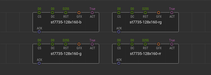
ST7735 breakout boards can differ from each other and require different initialization methods. Therefore, the library contains 4 quickstart nodes at once — , , , and . Each of these nodes works with a display of a certain type conventionally named “B”, “G”, “RG”, and “RR”. To find out which type your specific display belongs to, try each of these nodes until it works.
Wire your display to the microcontroller via hardware SPI bus and fill in the , , pin values according to the microcontroller ports. The is the “Chip Select” microcontroller port of the SPI interface. is the “Data/Command” microcontroller port responsible for sending data and commands to the display driver.
The pin is the “Reset” microcontroller port the display is connected to. This port is responsible for the display reset which can be required during device initialization. Not all ST7735 breakout boards have this pin. If your ST7735 breakout board has this pin, be sure to link it with a microcontroller and set the appropriate port value at the pin. If your breakout board does not have an pin, then leave the default value untouched.
The input pin of the type specifies the graphics to render and display on the device screen. The awaits a branch of the tree of graphical elements created using the graphics library. The value at the pin is responsible for the display screen update due to change of the incoming graphics at the pin.