net.ifinfo()
Return information about a network interface, specified by index.
Returns
if the given does not correspond to an interface. Otherwise,
a table containing …
-
, , and configured for this interface, as dotted quad strings
or if none is set. -
if DHCP was used to configure the interface, then will be a table containing…
-
— the DHCP server itself, as a dotted quad
-
— the IP address suggested for the client; likely, this equals
above, unless the configuration has been overridden. -
— the NTP server suggested by the DHCP server.
DNS servers are not tracked per-interface in LwIP and, as such, are not
reported here; use .
Распиновка ESP8266 NodeMCU
С внешним миром ESP8266 NodeMCU соединяют всего 30 выводов. Ниже показана распиновка отладочной платы.
Рисунок 6 – Распиновка ESP8266 NodeMCU
Для простоты мы сгруппируем выводы с аналогичными функциями.
Выводы питания – на плате расположено четыре вывода питания, а именно: один вывод VIN и три вывода 3.3V. Если у вас есть стабилизированный источник напряжения 5 В, вывод VIN можно использовать для непосредственного питания ESP8266 и его периферии. Выводы 3.3V – это выходы встроенного стабилизатора напряжения. Эти выводы могут использоваться для подачи питания на внешние компоненты.
GND – это вывод земли отладочной платы ESP8266 NodeMCU.
Выводы I2C используются для подключения всех видов датчиков и периферийных устройств на шине I2C в вашем проекте. Поддерживаются и I2C Master, и I2C Slave. Работа интерфейса I2C может быть реализована программно, а тактовая частота составляет максимум 100 кГц. Следует отметить, что тактовая частота I2C должна быть выше самой низкой тактовой частоты из ведомых устройств.
Выводы GPIO На ESP8266 NodeMCU имеется 17 выводов GPIO, которые можно назначать программно на различные функции, такие как I2C, I2S, UART, PWM, дистанционное инфракрасное управление, светодиодный индикатор и кнопка. Каждый включенный вывод GPIO может быть настроен либо на внутреннюю подтяжку к земле или к шине питания, либо установлен на высокоимпедансное состояние. При конфигурировании на вход для генерирования прерываний процессора он может быть настроен на срабатывание либо по фронту, либо по спаду.
Вывод ADC подает сигнал на имеющийся в NodeMCU, встроенный 10-разрядный прецизионный аналого-цифровой преобразователь последовательного приближения (SAR ADC). С помощью этого АЦП могут быть реализованы две функции: проверка напряжения питания на выводе VDD3P3 и проверка входного напряжения на выводе TOUT (но не одновременно).
Выводы UART ESP8266 NodeMCU имеет 2 интерфейса UART, то есть UART0 и UART1, которые обеспечивают асинхронную связь (RS232 и RS485) и могут обмениваться данными со скоростью до 4,5 Мбит/с. Для связи можно использовать UART0 (выводы TXD0, RXD0, RST0 и CTS0), который поддерживает управление потоком. UART1 (вывод TXD1) поддерживает только сигнал передачи данных, поэтому он обычно используется для печати журнала событий.
Выводы SPI ESP8266 имеет два интерфейса SPI (SPI и HSPI), поддерживающих и ведомый (slave), и ведущий (master) режимы. Эти интерфейсы SPI также поддерживают следующие функции SPI:
- 4 режима синхронизации передачи SPI;
- до 80 МГц и тактовые частоты, полученные делением 80 МГц;
- до 64 байт FIFO.
Выводы SDIO ESP8266 имеет защищенный цифровой интерфейс ввода/вывода (SDIO, Secure Digital Input/Output Interface), который используется для прямого подключения карт SD. Поддерживаются 4-битный 25 МГц SDIO v1.1 и 4-битный 50 МГц SDIO v2.0.
Выводы PWM На плате имеется 4 канала широтно-импульсной модуляции (PWM). Выход ШИМ может быть реализован программно и использован для управления двигателями и светодиодами. Частотный диапазон ШИМ регулируется от 1000 мкс до 10000 мкс, то есть от 100 Гц до 1 кГц.
Выводы управления используются, как ни странно, для управления ESP8266. Эти выводы включают в себя вывод включения микросхемы EN, вывод сброса RST и вывод пробуждения WAKE.
- Вывод EN – микросхема ESP8266 включена, когда на вывод EN подается высокий логический уровень. При низком логическом уровне микросхема работает на минимальной мощности.
- Вывод RST используется для сброса микросхемы ESP8266.
- Вывод WAKE используется для вывода чипа из глубокого сна.
NodeMCU PyFlasher
Self-contained NodeMCU flasher with GUI based on Python, esptool.py (see below) and wxPython. A runnable .exe is available for Windows and a .dmg for macOS.
No installation required on Windows and macOS! Instructions how to run it on other platforms are available on the project site.
- Install drivers for USB-to-serial. Which driver you need depends on the ESP8266 module or USB-to-serial converter you use.
- Connect USB cable to device and computer.
- Download then start PyFlasher
- Select serial port, browse for firmware binary and set the flash options.
Note that this tool is not an official NodeMCU offering. It’s maintained by a NodeMCU team member as an individual, though.
Flashing the Built in LED with Lua
Here’s a program to flash the built in LED. This is the way you
would initially think of writing
the code in C — non event driven. Even though it works don’t use this
in general. You need to think in terms of releasing processing time and
not making loops that do not exit (See next example for event driven
timer programming).
— NodeMCU ExamplesLEDpin=4— Declare LED pin no.
delayuS=500000— Set delay in microSecond. here 0.5 second
gpio.mode(LEDpin,gpio.OUTPUT)— Set LED pin as GPIO output pin
while(1)— Define infinite while loop
dogpio.write(LEDpin,gpio.HIGH)— Set LED pin HIGH i.e. LED OFF
tmr.delay(delayuS)— timer Delay
gpio.write(LEDpin,gpio.LOW)— Set LED pin LOW i.e. LED ON
tmr.delay(delayuS)— timer Delaytmr.wdclr()— Stop watchdog resetting the MCU
end
Save the above as file: led_flash1.lua
Note that the tmr.wdclr() function is used to stop the watchdog
reset which is needed it in this function to stop a reset because it is
not event driven — See next example for event driven blink.
Create Project
Select the «Initialize new PlatformIO project» button and create a new project. This option is also available in the PlatformIO main menu.
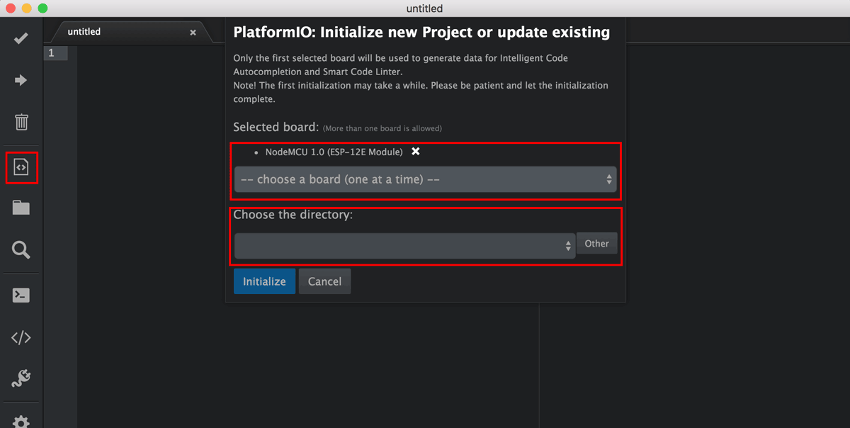
On the popup, select the board and the directory to place your project. Since we’re using a NodeMcu dev kit, select from the dropdown. As you can see, PlatformIO supports a wide variety of boards. Once you’ve got the options selected, click «Initialize». This will take a while the first time as PlatformIO downloads and installs the correct tools for your board. Once it’s done, you’ll see some automatically generated files.
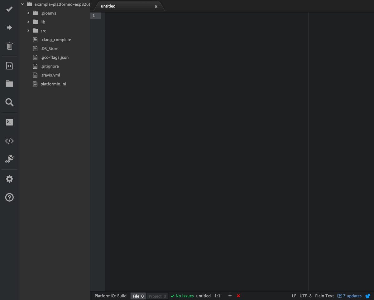
We’re now ready to write some code.
Code for ESP01 LED Blinking
int pin = 2;

// the setup function runs once when you press reset or power the board

void setup() {

  // initialize digital pin as an output.

  pinMode(pin, OUTPUT);

}

// the loop function runs forever

void loop() {

  digitalWrite(pin, HIGH);   // turn the LED on (HIGH is the voltage level)

  delay(1000);                       // wait for a second

  digitalWrite(pin, LOW);    // turn the LED off by making the voltage LOW

  delay(1000);                       // wait for a second

}
Sketch Uploading to ESP01
- First, you have to install FTDI232 programmer driver to install on your Windows PC. To download the driver visit this website: http://www.ftdichip.com/Drivers/VCP.htm.
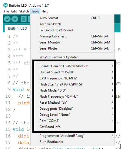
- Wired your ESP-01 module and FTDI232 according to the above picture and connect to the computer using a USB cable. Open the Arduino IDE. Open Tools drop-down menu and set the configuration as follow
Board: “Generic ESP8266 Module “

Upload Speed: “115200“

CPU Frequency: “80 MHz “

Flash Size: “512L (64K SPIFFS)“

Flash Mode: “DIO“

Flash Frequency: “40MHz“

Reset Method: “ck “

Debug Port: “Disabled“

Debug Level: “None”

Port: “(select on which com port FTDI module  is connected)”
Step 1: Control an LED From Web Browser
In this blog, we will see How to «Turn On and Turn Off» an LED that has connected to the Esp8266, the esp8266 has programmed from Arduino IDE to control the LED. We will connect the Esp8266 to the Wi-Fi router using SSID and password of our Home network Wifi , where the esp8266 connect to our wifi and create a webserver, which can be accessed by looking through the serial Monitor of the Arduino window or you can also log into your Wifi router and check for the list of clients connected to your Wi-Fi router. Here’s a window which explains the step by step procedure to connect the Esp8266 to the Wi-fi server and How to access the Webpage and control the LED connected to the Esp8266
For the above video I have used NodeMcu, you can use any type of Esp8266 to make this thing work in your web browser.
look for the mapping of pins in with your Esp8266 vendor, if the program not working properly for you , the fault will be with the pin mapping functionalities, Here I used the D7 pin which mapped to 13th pin when program from the Arduino IDE.
Connect your Esp8266 to Arduino IDE and Select the correct COM Port and board type and
upload the program.
Note change the SSID to your WiFi Name and password to your Wifi password. if you forget to change it , esp8266 will not connect connect your wifi.
—————————————————————————————————————————
<br>
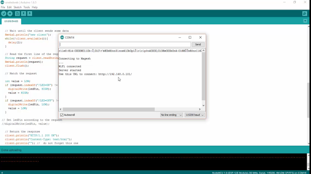
If everything completed you can turn to your serial monitor and check for the ip address that your devices has connected to . you will presented with an serial monitor that look exactly to the picture below.
if you like the above tutorial and if you want try out with cool projects you can also check this link here , that’s the amazon book link where you can use that book to make IoT with Esp8266 or Nodemcu, that books gives you basic coverage on how to do simple things and get yourself started with arduino and goes on developing projects like sending data to webserver and creating a webserver, uploading and controlling data from a webpage, how to interface TFT LCD and I2C devices and many more things can find on the link.
Step 3: Upload DS18b20 Temperature Sensor Data to Thingspeak From Esp8266 (nodemcu)
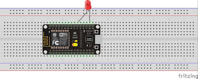
Hello all in this tutorial you will know how to use Ds18b20 Temperature data to thingspeak.com, you can follow above fritzing circuit diagram to control the Ds18b20 temperature sensor, This sensor follows one wire protocol which means you can connect many sensors as you want to the single pin and access temperature data calling the sensor by address. check the video below on how to work with this sensor and also proof of code working .
There is no much work to get work with this sensor, as there are plenty of example library that already available in the internet which anyone can make use and get started to work with this sensor.
Test the below code to know check whether you can get reading from the temperature sensor with ESP8266 or Nodemcu
if you get any error , make sure you have downloaded library for Ds18b20 Temperature sensor.
<iframe style="height: 510px; width: 100%; margin: 10px 0 10px;" allowtransparency="true" src="https://codebender.cc/embed/sketch:243987" frameborder="0"></iframe><br>
copy paste above code to your Arduino IDE and upload to your ESP8266 or Nodemcu if you are not sure about how to do this please check the video about to know how things work, if you don’t know yet to search search on this blog for getting started with Esp8266 in Arduino IDE.
below you can see the code for sending temperature data to thingspeak.com from Esp8266 or Nodemcu to do this you need have thingspeak api key which can get easily by registering to the website.
change SSID and password to your router password and also update the Nodemcu api key.
—————————————————————————————————————————
<iframe style="height: 510px; width: 100%; margin: 10px 0 10px;" allowtransparency="true" src="https://codebender.cc/embed/sketch:243988" frameborder="0"></iframe>
—————————————————————————————————————————
if you like the above tutorial and if you want try out with cool projects you can also check this link here , that’s the amazon book link where you can use that book to make IoT with Esp8266 or Nodemcu, that books gives you basic coverage on how to do simple things and get yourself started with arduino and goes on developing projects like sending data to webserver and creating a webserver, uploading and controlling data from a webpage, how to interface TFT LCD and I2C devices and many more things can find on the link.
Компоненты умного дома
Теперь я хотел бы подробнее остановится на компонентной схеме умного дома. Все компоненты уместились в следующей схеме:
Компоненты умного дома
Слева-направо: сначала идет ваше устройство на ESP8266, далее это прошивка ESP Easy (ее ставим на ESP8266), прошивку подключаем к MQTT-брокеру (например WQTT.ru или свой брокер на своем сервере), веб-сервис WQTT.ru уже имеет подключение к Алисе (на своем брокере это подключение придется сделать самостоятельно, что в общем несложно, потому что это наша привычная работа программиста), далее сервер логики Node RED, который подключен к MQTT-брокеру и управляет всем умным домом. И в конце можно поставить Homebridge для связи умного дома с Homekit.
Как вы наверное догадались, homebridge с голосовыми помощниками не обязательные компоненты. Главное это MQTT-брокер и Node RED. Эти два сервера вам обеспечат практический полный функционал и доступ к настройке любой логики.
Думаю общая картинка умного дома уже появилась и можно переходить к самим компонентам в отдельности. В этой статье рассмотрим MQTT-брокер и само устройство. В следующих статьях будем рассматривать настройку прошивки ESP Easy и Node RED. Этого будет достаточно, чтобы запустить простейший вариант умного дома.
В качестве устройства у нас будет светодиод, который встроен в ESP8266 и сидит на пине GPIO2. Этот светодиод будет имитировать освещение в гостиной например. Также подключим кнопку, которая будет включать этот светодиод. И еще в нашем устройстве будут два датчика: DHT11 и BMP085 (влажности и барометр с термометром).
В логику (которая будет хранится в Node RED) заложим управление кнопкой и светодиодом, оповещение по телеграму о резком похолодании в комнате и вывод значений датчиков в Homekit и Алису.
Загрузка новой прошивки
На плате есть две маленькие кнопки: User и Flash. Я не совсем понимаю, зачем нужна User, но если во время запуска платы нажать на Flash, она должна перейти в режим, в котором на нее теоретически можно загружать новые прошивки. Я говорю «теоретически», потому что сначала у меня ничего не работало. Чтобы я не пробовал, мне выдавало следующую ошибку:
$ python esptool.py --port /dev/tty.Repleo-CH341-XXXX write_flash 0x00000 nodemcu_latest.bin
Connecting...
Traceback (most recent call last):
  File "esptool.py", line 471, in
    esp.connect()
  File "esptool.py", line 149, in connect
    raise Exception('Failed to connect')
Exception: Failed to connect
Спустя какое-то время я сдался и взял нормальный адаптер Serial-USB, подключив его напрямую к контактам RX, TX и GND, минуя чип CH340G. Питание шло от Mac. Сделав сброс, я смог программировать модуль через ESPlorer абсолютно безо всяких проблем. Таким образом, в итоге и питание, и последовательная коммуникация шли через один единственный USB-кабель.
Установка драйвера
- Для Windows 7, 8, 8.1 и Linux драйвер не требуется
Драйвер для Mac OS X расположен в двух папках. Одна для Yosemite, другая – для всех остальных версий ОС. Установка прошла безо всяких проблем, потому что эти драйверы уже подписаны для Mac OS X. В противном случае вам бы пришлось переписать проверку безопасности в меню System Settings (вкладка Security Tab).
Когда драйвер будет установлен, модуль отобразится в ОС следующим образом:
- /dev/tty.Repleo-CH341-XXXX
- /dev/cu.Repleo-CH341-XXXX
Странно, впрочем, что ESPlorer увидел только драйвер cu.Repleo, но я все же смог с его помощью подключиться к AT-прошивке на скорости 9600 бод. Затем нарисовалась другая проблема…
node.startupcounts()
Query the performance of system startup.
Important
This function is only available if the firmware is built with defined. This would normally be done by uncommenting the line in .
Example
This might generate the output (formatted for readability):
The crucial entry is the one for which is when the application had started running. This was on a Wemos D1 Mini with flash running at 80MHz. The startup options were all turned on.
Note that the clock speed changes in to 160MHz. The total time was (approximately): . With startup options of 0, the time is 166ms. These times may be slightly optimistic as the clock is only 52MHz for a time during boot.
node.info()
Returns information about hardware, software version and build configuration.
Parameters
A designator for a group of properties. May be one of , , . It is currently optional; if omitted the legacy structure is returned. However, not providing any value is deprecated.
Returns
If a is given the return value will be a table containing the following elements:
-
for =
- (number)
- (number)
- (number)
- (number) 0 = QIO, 1 = QOUT, 2 = DIO, 15 = DOUT.
- (number)
-
for =
- (number) Flash offset of selected LFS region
- (number) Mapped memory address of selected LFS region
- (number) size of selected LFS region
- (number) actual size used by current LFS image
-
for =
- (string)
- (string)
- (string) release name +additional commits e.g. «2.0.0-master_20170202 +403»
- (string) commit timestamp in an ordering format. e.g. «201908111200»
- (number)
- (number)
- (number)
-
for =
- (boolean)
- (number) as defined at build time
- (string) comma separated list
- (string) or
Attention
Not providing a is deprecated and support for that will be removed in one of the next releases.
- for =
- (number)
- (number)
- (number)
- (number)
- (number)
- (number)
- (number)
- (number)
Начало работы с Termite
В оригинальной статье о прошивке ESP8266 была рекомендована PuTTY; и, если она у вас она есть, и вы хотите её использовать, она здесь будет отлично работать. Тем не менее, Termite в этом плане более удобное приложение и будет использоваться далее в этой статье. Termite бесплатен и для личного, и для коммерческого использования.
В последующих этапах предполагается, что модуль ESP-01 запрограммирован так же, как обычно, поставщиком. Если вы (или кто-то еще) внесли изменения в стандартные настройки программы, вам необходимо будет поэкспериментировать, чтобы определить текущие настройки вашего модуля ESP-01.
После проверки своей схемы программирования ESP-01, как описано выше, включите её. Запустите на своем компьютере Termite и нажмите кнопку Settings (Настройки); вы должны увидеть окно, похожее на приведенное ниже. Убедитесь, что COM порт, к которому подключен USB-TTL конвертер, правильно выбран в окне настроек последовательного порта. Выставьте все остальные параметры, как показано в окне настроек последовательного порта ниже, и нажмите OK, чтобы закрыть окно настроек последовательного порта.
Настройки последовательного порта
На этом этапе курсор должен мигать в нижней части окна Termite; если нет, кликните на нижней части окна Termite, чтобы поместить туда курсор. Введите и нажмите Enter на клавиатуре; если всё хорошо, ESP-01 ответит в окне Termite. Если это произойдет, можете вздохнуть с облегчением, потому что вы только что преодолели главное препятствие.
Затем введите и нажмите Enter. ESP-01 должен ответить чем-то очень похожим, что показано на рисунке ниже.
Отклик модуля ESP-01
Команда говорит ESP8266 сообщить о версии набора AT-команд, который он содержит, какой SDK (Software Development Kit) был загружен в него, какая компания собрала модуль ESP, и когда SDK был загружен в модуль. Наконец, как обычно, ESP8266 завершает свой ответ с помощью .
Если ESP-01 ответил правильно, то можно закончить с Termite (если вы не хотите еще поэкспериментировать). Далее он понадобится снова для подтверждения успешной прошивки.
Docker
The Docker NodeMCU build image is the easiest method to build NodeMCU related components locally on your preferred platform.
Offering:
- build NodeMCU firmware based on locally cloned sources and configuration
- cross-compile Lua files into LFS image locally
Detailed instructions available in the image’s README. As for available config options and study the comments in .
For LFS
- In edit the line and adjust the size to that needed. Note that this must be a multiple of 4Kb.
- Build as you would otherwise build with this image (i.e. see its README)
Note that this Docker image is not an official NodeMCU offering. It’s maintained by a NodeMCU team member as an individual, though.
gpio.trig()
Establish or clear a callback function to run on interrupt for a pin.
This function is not available if GPIO_INTERRUPT_ENABLE was undefined at compile time.
Parameters
- 1-12, pin to trigger on, IO index. Note that pin 0 does not support interrupts.
-
«up», «down», «both», «low», «high», which represent rising edge, falling edge, both
edges, low level, and high level trigger modes respectivey. If the type is «none» or omitted
then the callback function is removed and the interrupt is disabled. -
callback function when trigger occurs. The level of the specified pin
at the interrupt passed as the first parameter to the callback. The timestamp of the event is passed
as the second parameter. This is in microseconds and has the same base as for . This timestamp
is grabbed at interrupt level and is more consistent than getting the time in the callback function.
This timestamp is normally of the first interrupt detected, but, under overload conditions, might be a later one.
The eventcount is the number of interrupts that were elided for this callback. This works best for edge triggered
interrupts and enables counting of edges. However, beware
of switch bounces — you can get multiple pulses for a single switch closure. Counting
works best when the edges are digitally generated.
The previous callback function will be used if the function is omitted.
Что такое NTP?
NTP означает Network Time Protocol (протокол сетевого времени). Это стандартный интернет-протокол для синхронизации часов компьютера с неким эталоном в сети.
Данный протокол может использоваться для синхронизации всех сетевых устройств с всемирным координированным временем (UTC) с точностью до нескольких миллисекунд (50 миллисекунд в общедоступном Интернете и менее 5 миллисекунд в среде LAN).
Всемирное координированное время (UTC) – это всемирный стандарт времени, тесно связанный с GMT (средним временем по Гринвичу). UTC не меняется, оно одинаково во всем мире.
NTP устанавливает часы компьютеров в формате UTC, любое смещение местного часового пояса или смещение летнего времени применяется уже клиентом. Таким образом, клиенты могут синхронизироваться с серверами независимо от местоположения и разницы часовых поясов.
Disadvantages of the NodeMcu module
The main disadvantage is the ability to execute only LUA scripts located in RAM. This type of memory is small, the volume is only 20 KB, so writing large scripts causes a number of difficulties. First of all, the whole algorithm will have to be divided into linear blocks. These blocks must be written to separate system files. All of these modules are executed using the dofile operator.
When writing, you must follow the rule – when exchanging data between modules, you need to use global variables, and when calculating inside modules, you need to use local variables. It is also important to call the collectgarbage function (garbage collector) at the end of each script you write.
node.sleep()
Put NodeMCU in light sleep mode to reduce current consumption.
- NodeMCU can not enter light sleep mode if wifi is suspended.
- All active timers will be suspended and then resumed when NodeMCU wakes from sleep.
Attention
This is disabled by default. Modify in to enable it.
Parameters
- 1-12, pin to attach wake interrupt to. Note that pin 0(GPIO 16) does not support interrupts.
-
type of interrupt that you would like to wake on. (Optional, Default: )
- valid interrupt modes:
- Rising edge
- Falling edge
- Both edges
- Low level
- High level
- valid interrupt modes:
- Callback to execute when WiFi wakes from suspension. (Optional)
-
preserve current WiFi mode through node sleep. (Optional, Default: true)
- If true, Station and StationAP modes will automatically reconnect to previously configured Access Point when NodeMCU resumes.
- If false, discard WiFi mode and leave NodeMCU in . WiFi mode will be restored to original mode on restart.
Похожие записи:
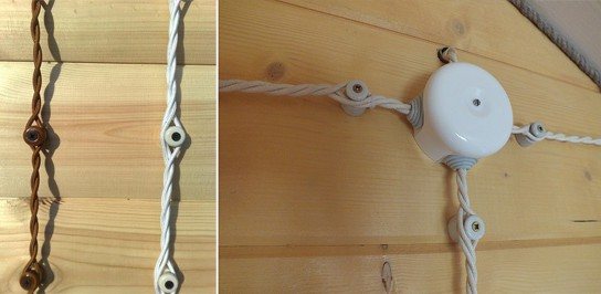 Как правильно крепить кабель канал к стене?
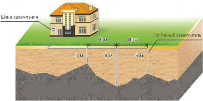 Системы заземления типа tn-s, tn-c, tn-c-s
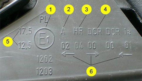 Маркировка фар: расшифровка аббревиатур и сокращений! важно!
 Прозвонка проводов и кабелей (прибор)
 Подсветка приборной панели ваз 2107: какие лампы нужны и как заменить
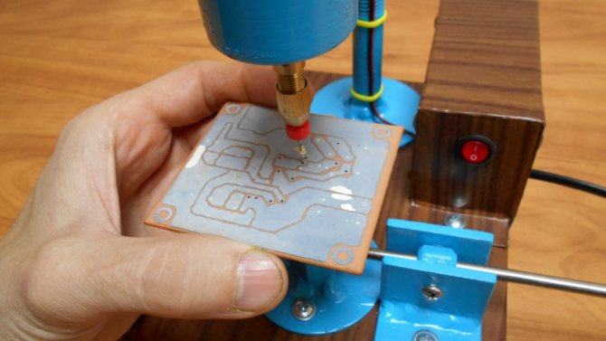 Можно ли собрать сверлильный станок чпу для печатных плат своими руками?