Step 6: Introducing BluetoothSerial
The most important function of BluetoothSerial plugin is:
bluetoothSerial.write();
Whatever we will send in write function, the plugin will write that on serial output of bluetooth module.
So, in this case, following code bit is doing all the work. When a user presses the «LED ON» button, the script will write «a» onto the Arduino serial using BluetoothSerial plugin and in the other case it will write the character «b», which our Arduino sketch understands as the argument to switch the LED to off status.
app.initialize();
app.ledOn = function(){
      bluetoothSerial.write("a");
}
app.ledOff = function()
      bluetoothSerial.write("b");
}
5Подключаемся к bluetooth-модулю по bluetooth с компьютера
Для подключения к bluetooth модулю можно использовать различные программы, которые могут подключаться к COM-порту. Например, такие как HyperTerminal, PuTTY, Tera Term, Termite и другие. Они все бесплатные и свободно распространяются в интернете.
Удобство программы TeraTerm в том, что она автоматически выводит список COM-портов, которые назначены модулю bluetooth вашего компьютера. Запускаем программу, выбираем подключение Serial, из списка выбираем соответствующий bluetooth COM-порт, нажимаем OK.
Подключение к bluetooth-модулю с помощью программы TeraTerm
Программа PuTTY при запуске также спрашивает номер порта (COM4, у вас будет свой), скорость подключения (9600), тип соединения (Serial). Затем нажимаем кнопку Соединиться.
Подключение к bluetooth-модулю с помощью программы PuTTY
В случае ошибки при подключении программа выведет соответствующее оповещение. Если соединение вашего компьютера с bluetooth-модулем произошло успешно, то вы увидите перед собой поле терминала. Введите с клавиатуры в это поле число 1 – и светодиод на 13 выводе Arduino загорится, введите 0 – погаснет.
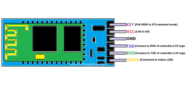
HC-05 Pinout with Description:
| PIN NO. | Pin Name | Pin Description |
| 1. | KEY/En | This pin is used to bring the Bluetooth module in AT commands mode. By default, this pin operates in data mode. The Key/EN pin should be high to operate Bluetooth in command mode. In HC-05, the default baud speed in command mode is 38400bps and 9600 in data mode. |
| 2. | VCC | Used to power the Bluetooth module. Give 5V / 3.3 V to this Pin. |
| 3. | GND | The ground pin of the module |
| 4. | TXD | Connect this pin with the RXD pin of the Microcontroller. This pin transmits Serial data (wireless signals received by the Bluetooth module are converted by module and transmitted out serially on this pin) |
| 5. | RXD | Connect this pin to the TXD pin of the Microcontroller. The HC-05 Bluetooth module receives the data from this pin and then transmits it wirelessly. |
| 6. | STATE | It is used to check if the module is connected or not. It acts as a status indicator. |
Step 3: Send Serial Commands to Arduino Using Serial Monitor (or Any Terminal)
Upload the following sketch to the Arduino using USB cable.
Caution: Disconnect the HC-05 bluetooth module Rx and Tx pins from Arduino Uno as this particular board has only one hardware serial and connecting something to it while uploading a sketch will create conflict or your can using Arduino SoftwareSerial to avoid conflicts. Reconnect these pins once you are done uploading the sketch.
/*Arduino Turn LED On/Off using Serial Commands
Created April 22, 2015
Hammad Tariq, Incubator (Pakistan)
It’s a simple sketch which waits for a character on serial
and in case of a desirable character, it turns an LED on/off.
Possible string values:
a (to turn the LED on)
b (tor turn the LED off)
*/
char junk;
String inputString=»»;
void setup() // run once, when the sketch starts
{
Serial.begin(9600); // set the baud rate to 9600, same should be of your Serial Monitor
pinMode(13, OUTPUT);
}
void loop()
{
if(Serial.available()){
while(Serial.available())
{
char inChar = (char)Serial.read(); //read the input
inputString += inChar; //make a string of the characters coming on serial
}
Serial.println(inputString);
while (Serial.available() > 0)
{ junk = Serial.read() ; } // clear the serial buffer
if(inputString == «a»){ //in case of ‘a’ turn the LED on
digitalWrite(13, HIGH);
}else if(inputString == «b»){ //incase of ‘b’ turn the LED off
digitalWrite(13, LOW);
}
inputString = «»;
}
}
After uploading, open Arduino Serial Monitor, set the baud rate to 9600 and command line ending drop down (the one next to baud rate) to «No line ending», that means we will not be sending and /r or /n characters with our serial command.
Now type character «a» in the serial monitor and press send, the your LED should turn on, then send «b», the LED should turn off.
I have also attached the sketch file with this step, this is all we need at Arduino sketch level for turning LED on/off even through the Bluetooth and mobile app. In next step, we will communicate via bluetooth in order to play with our LED.
Характеристики
Давайте подробнее разберёмся, какие характеристики имеет такой bluetooth модуль для ПК и различных проектов. Сами разработчики заявляют, что выдержали коммерческий стандарт в hc 05. Соответственно, для управления устройством будет достаточно специальной программы на смартфоне или компьютере, которая позволит отправлять и получать данные с датчика. Однако существует ограничение в области применения, ведь устойчивый сигнал, без использования усилителей, можно поймать лишь на 9 метрах от чипа
Учитывайте, что это сырые цифры, в которых во внимание не берутся преграды на пути волн
Сами hc чипы полностью совместимы с любыми адаптерами, что поддерживают SPP. На самой плате устройства размещается небольшая антенна, припаянная к верхнему слою в виде дорожки, похожей на змею. Характеристики девайса заявлены следующие:
- Активные частоты радиосвязи находятся в диапазоне 2.4-2.48 ГГц.
- Канал приспособлен к адаптивному переключению.
- Условная дальность связи – 10 метров, но в этой цифре не учитываются преграды и помехи.
- Максимальная скорость при обмене информацией – 115300 бод.
- Хранить чип можно в температурном диапазоне от — 40 до +85 градусов, а вот использовать – от -20 до +70.
- Для работы необходимо будет напряжение в 3.3 В, что мы рассмотрим чуть ниже.
Работа проекта
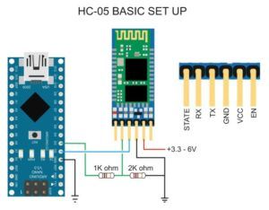
Шаг 1. Соберите схему, приведенную на рисунке выше. Перед загрузкой кода программы в плату Arduino отсоедините контакты Rx и Tx. После загрузки программы снова их подсоедините.
Шаг 2. Скачайте по приведенной в начале статье ссылки приложение для смартфона под названием “Arduino Bluetooth Voice Controller”. Либо вы непосредственно можете скачать его со своего смартфона по его названию.
Шаг 3. Запустите скачанное приложение, у вас на смартфоне появится его экран, показанный на приведенном ниже рисунке. Кликните на “connect to Bluetooth device” (соединиться с Bluetooth устройством), выберите после этого свой Bluetooth модуль и затем проверьте подсоединился ли он к приложению или нет. Затем кликните на иконку микрофона и после этого вы можете передавать голосовые команды Bluetooth модулю HC-06.
Примечание: когда вы будете подключаться к Bluetooth модулю HC-06 в первый вам необходимо будет ввести пароль для подключения к модулю – используйте в качестве пароля 0000 или 1234.
Шаг 4. Передавая голосовые команды Bluetooth модулю HC-06, который затем транслирует их по последовательному порту связи плате Arduino, которая выполняет принятую команду по включению/выключению светодиодов. Список реализованных в программе команд и действия, которые при их поступлении следует выполнить, представлен в следующей таблице.
| № п/п | Команда | Действие |
| 1 | all LED turn on | включить оба светодиода |
| 2 | all LED turn off | выключить оба светодиода |
| 3 | turn on Red LED | включить красный светодиод |
| 4 | turn on green LED | включить зеленый светодиод |
| 5 | turn off red LED | выключить красный светодиод |
| 6 | turn off green LED | выключить зеленый светодиод |
Аналогичным образом, изменяя код программы, вы можете добавить в этот проект любые другие команды и, соответственно, добавить в схему любые другие устройства (электрическая лампочка, телевизор, кондиционер и т.д.), которыми вы хотите управлять с помощью голоса.
Arduino Bluetooth Projects
To end today’s guide to Arduino Bluetooth modules, here are two simple Arduino Bluetooth projects you can get started!
Control your robotic car through Bluetooth
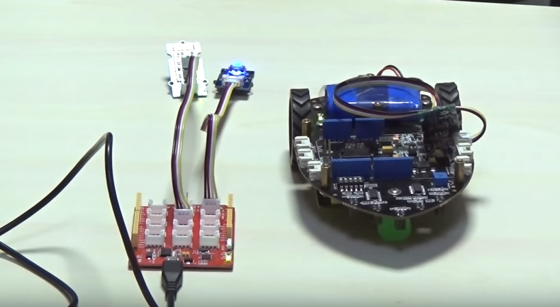
Robotics and Arduino is a fun and interesting hobby which is very commonly seen nowadays. With this project, you can experience that through the help of Bluetooth!
Here’s what you need:
Hardware components:
- 2 Seeeduino Lotus
- 2 Grove – Serial Blueseeed (CSR BC417)
- Shield Bot or other cars
- Grove – Mini Track Ball
Software apps and other services:
Arduino IDE
Interested to find out more? Check out the full tutorial by Kevin-Lee on Seeed Community Hub!
Fun, Little, Scary Horror Doll
Want to pull a little prank on someone and get their hilarious reaction? This project is the one for you!
It uses a controller to small doll eyes emitting light of terror. It can swing and turn hands, head, and emits a scream of terror. Mount a PIR sensor above and when someone is close to it, it’ll jump out to scare them!
Here’s what you need:
Hardware components:
- Grove – PIR Motion Sensor
- 2 Grove – Chainable RGB LED
- Grove – Servo
- Grove – Serial Blueseeed (CSR BC417)
This project uses Wio Link, however, you can still use an Arduino board with a Grove – Base Shield
Interested to find out more? Check out the full tutorial by shijian.fang on Seeed Community Hub!
3Скетч для Arduinoдля работы по bluetooth
Напишем такой скетч и загрузим в память Arduino:
const int ledPin = 13; // вывод встроенного светодиода
char incomingbyte; // переменная для данных Bluetooth

void setup() {
  pinMode(ledPin, OUTPUT);
  Serial.begin(9600);
}

void loop() {
  if (Serial.available() > 0) { // если порт доступен
    incomingbyte = Serial.read(); // считываем с порта данные
      switch(incomingbyte) {
      case '1': // если приходит "1"
          digitalWrite(ledPin, HIGH); //
          break;
      case '0': // если приходит "0"
          digitalWrite(ledPin, LOW); //
          break;
      }
  }
}
Включаем собранную схему с Arduino и подключённым к нему bluetooth-модулем. Правильно подключённый модуль сразу входит в режим ожидания подключения, о чём будет свидетельствовать ритмично мигающий светодиод статуса.
Module HC-06 configuration
Configuring the module HC-06 can be interesting to verify that it is working, hooked up correctly and to modify its parameters such as its name (useful when your are using several modules), PIN code and communication speed (baudrate). To allow configuration, the module HC-06 should be powered but not paired (la LED is blinking).
The following code allows you to modify the parameters using the serial monitor.
To test serial communication, enter AT in the serial monitor and click on the send or press enter. Be sure to select “No end line” and the correct baudrate in the communication options. Module should answer OK. If it is not working check the wiring and the module version.
To modify the module name, enter AT+NAMEmodule_name.Module should answer OKsetname. (Ex: If you want to change module name into BTM1 enter AT+NAMEBTM1)
To modify the module PIN code, enter AT+PINxxxx. Module should answer OKsetPIN. (Ex: If you want to change PIN into 0000 enter AT+PIN0000)
To modify the module communication speed (only if required), enter AT+BAUDx. Ex: If you want to change baudrate into 9600 enter AT+BAUD4. Module should answer OK9600. (Note: 1 for 1200, 2 for 2400, 3 for 4800, 4 for 9600, 5 for 19200, 6 for 38400, 7 for 57600, 8 for 115200)
WARNING:Different versions of the Bluetooth module HC-06 exit and the list of AT commands may vary. Check the serial number written on the module and the firmware version by entering AT+VERSION.
For instance, the module HC-06 labelled ZS-040with firmware version 3.0-20170609 returns ERROR(0) when sending command AT+NAMExxxx (with xxxx the new name of the module). The AT commands to configure such module are:
- AT+NAME=xxxx to set the name of the module
- AT+PSWD:”xxxx” to set the pin code of the module
Do not hesitate to leave a comment if you encounter an issue while configuring your Bluetooth module HC-06.
2Схема подключенияbluetooth-модуля к Arduino
Подключим bluetooth модуль к Arduino по приведённой схеме
Обратите внимание, что передатчик (Tx) Ардуино подключается к приёмнику (Rx) модуля, и наоборот
Схема подключения модуля bluetooth к Arduino
На выводе Status появляется высокий уровень, когда модуль сопряжён с другим bluetooth устройством, и низкий – когда не сопряжён. Можно считывать его значение, подключив к пину Arduino и назначив ему режим работы pinMode(pinStatus, INPUT) и таким образом узнавать состояние модуля. Но не на всех модулях индикатор статуса работает корректно, поэтому мы не будем его использовать в данном примере.
В результате должно получиться примерно как на фотографии.
Bluetooth модуль подключён к Arduino
Step 4: Getting HC-5 to Work With Arduino and Testing the Commuincation
In this step, we are focusing on getting HC-05 to work with Arduino and testing all the communication before we move towards building our mobile app.
Important: There is no extra step or coding required for HC-05 to work, it’s a simple serial port module, which means if you pair it and then connect to it using any serial port terminal, it will work just like Arduino Serial Monitor.
Follow these mini-steps:
- Connect the Rx and Tx pins of HC-05 back to Arduino (if you haven’t did this already).
- Pair the device with your mobile phone (in my case I am using Android OS and my phone is Samsung SII).
- Open Bluetooth Terminal app.
- From the menu, tap on «Connect a device — Insecure».
- You will see a pop-up of «Paired Devices», tap on «HC-05», after a second you will get a toast notifying «Connected to HC-05».
- Now type «a» and send, the LED will turn on, similarly, send «b» to turn the LED off.
In the next step will start building our cross-platform HTML5 app by installing and using Cordova and Evothings Studio.
Source Code
The Joystick code is exactly the same as the one for the Bluetooth communication. We just read the analog values of the joystick and send them to the other module using the Serial.write() function.
Transmitter code:
/*
   Arduino Robot Car Wireless Control using the HC-12 long range wireless module

                == Transmitter - Joystick ==

   by Dejan Nedelkovski, www.HowToMechatronics.com
*/

int xAxis, yAxis;

void setup() {
  Serial.begin(9600); // Default communication rate of the Bluetooth module
}

void loop() {
  xAxis = analogRead(A0); // Read Joysticks X-axis
  yAxis = analogRead(A1); // Read Joysticks Y-axis

  // Send the values via the serial port to the slave HC-05 Bluetooth device
  Serial.write(xAxis/4); // Dividing by 4 for converting from 0 - 1023 to 0 - 256, (1 byte) range
  Serial.write(yAxis/4);
  delay(20);
}
On the other side, with the while() loop we wait until the data arrive, then read it using Serial.read() function and convert it back into the 0 to 1023 range, suitable for the motor control code below.
Receiver code:
/*
   Arduino Robot Car Wireless Control using the HC-12 long range wireless module

             == Receiver - Arduino robot car ==

   by Dejan Nedelkovski, www.HowToMechatronics.com
*/

#define enA 9
#define in1 4
#define in2 5
#define enB 10
#define in3 6
#define in4 7

int xAxis, yAxis;
int  x = 0;
int  y = 0;

int motorSpeedA = 0;
int motorSpeedB = 0;

void setup() {
  pinMode(enA, OUTPUT);
  pinMode(enB, OUTPUT);
  pinMode(in1, OUTPUT);
  pinMode(in2, OUTPUT);
  pinMode(in3, OUTPUT);
  pinMode(in4, OUTPUT);

  Serial.begin(9600); // Default communication rate of the Bluetooth module
}

void loop() {
  // Default value - no movement when the Joystick stays in the center
  xAxis = 510;
  yAxis = 510;

  // Read the incoming data from the
  while (Serial.available() == 0) {}
  x = Serial.read();
  delay(10);
  y = Serial.read();
  delay(10);

  // Convert back the 0 - 255 range to 0 - 1023, suitable for motor control code below
  xAxis = x * 4;
  yAxis = y * 4;

  // Y-axis used for forward and backward control
  if (yAxis < 470) {
    // Set Motor A backward
    digitalWrite(in1, HIGH);
    digitalWrite(in2, LOW);
    // Set Motor B backward
    digitalWrite(in3, HIGH);
    digitalWrite(in4, LOW);
    // Convert the declining Y-axis readings for going backward from 470 to 0 into 0 to 255 value for the PWM signal for increasing the motor speed
    motorSpeedA = map(yAxis, 470, 0, 0, 255);
    motorSpeedB = map(yAxis, 470, 0, 0, 255);
  }
  else if (yAxis > 550) {
    // Set Motor A forward
    digitalWrite(in1, LOW);
    digitalWrite(in2, HIGH);
    // Set Motor B forward
    digitalWrite(in3, LOW);
    digitalWrite(in4, HIGH);
    // Convert the increasing Y-axis readings for going forward from 550 to 1023 into 0 to 255 value for the PWM signal for increasing the motor speed
    motorSpeedA = map(yAxis, 550, 1023, 0, 255);
    motorSpeedB = map(yAxis, 550, 1023, 0, 255);
  }
  // If joystick stays in middle the motors are not moving
  else {
    motorSpeedA = 0;
    motorSpeedB = 0;
  }

  // X-axis used for left and right control
  if (xAxis < 470) {
    // Convert the declining X-axis readings from 470 to 0 into increasing 0 to 255 value
    int xMapped = map(xAxis, 470, 0, 0, 255);
    // Move to left - decrease left motor speed, increase right motor speed
    motorSpeedA = motorSpeedA - xMapped;
    motorSpeedB = motorSpeedB + xMapped;
    // Confine the range from 0 to 255
    if (motorSpeedA < 0) {
      motorSpeedA = 0;
    }
    if (motorSpeedB > 255) {
      motorSpeedB = 255;
    }
  }
  if (xAxis > 550) {
    // Convert the increasing X-axis readings from 550 to 1023 into 0 to 255 value
    int xMapped = map(xAxis, 550, 1023, 0, 255);
    // Move right - decrease right motor speed, increase left motor speed
    motorSpeedA = motorSpeedA + xMapped;
    motorSpeedB = motorSpeedB - xMapped;
    // Confine the range from 0 to 255
    if (motorSpeedA > 255) {
      motorSpeedA = 255;
    }
    if (motorSpeedB < 0) {
      motorSpeedB = 0;
    }
  }
  // Prevent buzzing at low speeds (Adjust according to your motors. My motors couldn't start moving if PWM value was below value of 70)
  if (motorSpeedA < 70) {
    motorSpeedA = 0;
  }
  if (motorSpeedB < 70) {
    motorSpeedB = 0;
  }
  analogWrite(enA, motorSpeedA); // Send PWM signal to motor A
  analogWrite(enB, motorSpeedB); // Send PWM signal to motor B
}
So that’s pretty much everything for this tutorial. Feel free to ask any question in the comments section below.
Схема сборки машинки на Ардуино
Если у вас есть все необходимые детали (в проекте можно обойтись без светодиодов и резисторов), то далее мы рассмотрим, как сделать машинку из ардуино своими руками. Для начала следует припаять к контактам моторчиков провода и зафиксировать их изолентой, чтобы контакты не оторвались. Провода необходимо соединить с клеммниками M1 и M2 на Motor Shield (полярность потом можно будет поменять).
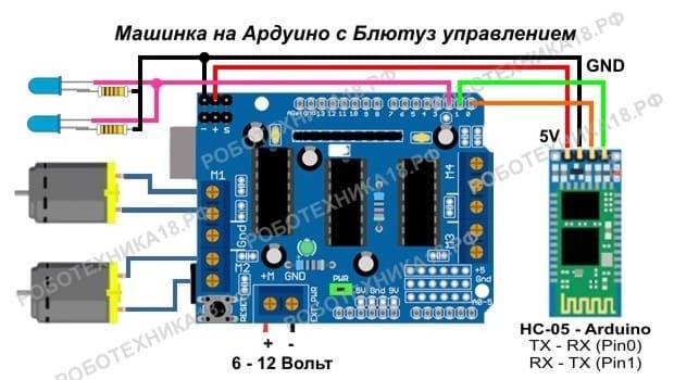
Схема сборки машинки с Блютуз управлением
Питание на Bluetooth модуль идет от контактов для сервопривода, в проекте серво нам не понадобятся. А на питание идет стабилизированное напряжение 5 Вольт, что нам подходит. К портам TX и RX удобнее будет припаять коннекторы «мама», а к портам «Pin0» и «Pin1» на Motor Shield припаять штырьки (BLS). Таким образом, вы сможете легко отключать Bluetooth модуль от Arduino при необходимости загрузки скетча.
Управление светодиодами идет от порта «Pin2», здесь провод можно припаять напрямую к порту. Если вы делаете несколько машинок с Блютуз, которыми будете управлять одновременно, то рекомендуем сделать перепрошивку модуля HC-05. Делается прошивка модуля очень просто, а затем вы уже не будете путать машинки, так как у каждой будет отображаться свое уникальное имя на Андроиде.
Pin Funtions
| Pin | Description |
|---|---|
| State | can be connected to the Arduino Input in order to know the state of the connection. Paired or disconnected. |
| Rx | Receive Pin of the module. It is recommended to use a voltage divider as shown in the hookup. |
| Tx | Can be connected directly to the Arduino Rx Pin |
| GND | connected to GND pin of Arduino |
| 5v | This breakout board has a internal 3.3v regulator on board. |
| EN | Enables or Disables the module. Rarely Used. |
Simple Data Transfer Example
We will start with a very simple example of establishing a serial connection between the HC-05 and the Smart Phone and send/receive message. You can take the example forward to control devices or log any data that you wish.
Slave Configuration
So for example, if we type just “AT” which is a test command we should get back the message “OK”. Then if we type “AT+UART?” we should get back the massage that shows the default baud rate which is 38400. Then if we type “AT+ROLE?” we will get back a massage “+ROLE=0” which means that the Bluetooth device is in slave mode. If we type “AT+ADDR?” we will get back the address of the Bluetooth module and it should looks something like this: 98d3:34:905d3f.
Now we need to write down this address as we will need it when configuring the master device. Actually that’s all we need when configuring the slave device, to get its address, although we can change many different parameters like its name, baud rate, pairing password and so on, but we won’t do that for this example.
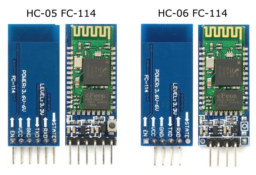
Step 1: Identifying Your Module
First thing you need to do is identify your module. It can be either HC05 or HC06. Both the modules are same in functionality except the pinout. Also HC05 can act as both master and slave whereas HC06 functions only as slave. It’s hard to differentiate between the two only by seeing. One probable way would be checking the back of the breakout board. If it has «JY-MCU» written on the back, it’s probably a HC06. Mine has «ZS-040» written and it is a HC05. And the HC06 module I tested had a bluetooth sign behind with three pcb footprints(refer to figure2). To confirm the device identity, you can power up the module, search for new device on your pc or mobile, and look for HC05 or HC06 on found device list.
Introduction: Remote Controlled LED Using HC-05 Bluetooth, Arduino and Mobile Phone App
By hammadtqHammad TariqFollow
More by the author:
About: I am a digital nomad and I often find myself navigating myself the fields of IoT, IIoT, VR, Voice Activation, Web and Mobile Apps and you know.. you got the idea 🙂
More About hammadtq »
Technology is progressing at break-neck speed, everyone of us has smart phones now-a-days, there are cool apps which let us stay in contact with our friends and family, get latest weather information or stay-updated with latest news but what’s next? All of these are old-school techs by now, what is the next use of this amazing processing speed and cutting-edge communication method we carry around with us all times? If I say you can control the lights of your home, know that if heating is on? or if your mobile phone automatically shuts off your air conditioner? Ring bells?
Of course, here on Instructables, we all know these uses and using this tutorial we will build a circuit and control it through the mobile app and we will do it very rapidly, let’s say you will be able to control lights of your home in under 20-30 minutes? Uh-oh, not really the lights but for brevity’s sake we will be controlling an LED for now and you can add all kinds of circuitry later!
Let’s start, we will need:
- An Arduino, for this tutorial I will be using Arduino Uno.
- A solder less breadboard, 220 ohm to 1K ohm resistor and a LED
Let’s go forward to the next step and start building our circuit!
Сравнение модулей Bluetooth HC 05 и HC 06
Модули HC 05 и HC 06 являются наиболее используемыми, их чаще остальных можно найти в продаже. Принцип действия этих модулей схож, оба модуля основаны на одинаковом чипе, но есть и важные отличия. В первую очередь, модуль HC 05 может работать в двух режимах работы – и в качестве ведущего (master), и в качестве ведомого (slave).
Оба модуля представляют собой две спаянные платы. Одна из них – заводская с микросхемой, другая нужна для самодельных устройств, она оснащена ножками GPIO со стандартным шагом 2,54 мм и стабилизатором напряжения.
Модули HC-05 и HC-06
Модуль HC-05 стоит несколько дороже, но он имеет большее количество полезных рабочих функций.
Распиновка модуля HC-05:
- EN – управление питанием;
- Питание VCC;
- GND;
- RX, TX;
- STATE – индикация;
- KEY – активирует режим управления при помощи АТ-команд. При KEY=0 – передача данных, при KEY=1 – АТ-команды.
Скорость передачи АТ команд по умолчанию для HC-05 равна 38400, для HC-06 – 9600. Важным моментом является то, что в конце АТ команд для HC-05 должны быть символы CRLF.
Основные характеристики HC-05:
- Рабочие частоты 2,4 – 2,48 ГГц;
- Мощность передачи 0,25 – 2,5мВт;
- Дальность 10 м;
- Максимальная скорость обмена данными 115200 бод;
- Питание 3,3В;
- Ток 30-40 мА;
- Рабочие температуры от -25С до 75С.
Подключение обоих модулей к плате Ардуино одинаково.
Вариант подключение модуля с использованием делителя.Представлен вариант для Arduino Nano, но он подойдет и к плате Uno.
Пояснение части кода программы
Полный код программы вместе с видео, демонстрирующим работу схему, приведен в конце статьи. В этой же части статьи мы лишь поясним как правильно объявить переменные в программе, в которых будут храниться символы, поступающие от Bluetooth-модуля.
C++
#include <io.h>
// глобальные переменные объявляются здесь
// стандартные функции ввода/вывода
#include <stdio.h>
void main(void)
{
char var; // локальные переменные объявляются здесь
|
1 |
#include <io.h> voidmain(void) { charvar;// локальные переменные объявляются здесь |
Остальная часть кода программы достаточно проста и легка для понимания. Теперь давайте рассмотрим последние строки кода, в которых вы можете найти цикл while – в этом цикле сосредоточена главная часть кода программы, поскольку в нем мы непрерывно проверяем поступающие символы от Bluetooth-модуля и включаем/выключаем светодиод соответственно.
C++
while (1)
{
scanf(«%c»,&var); // эта функция используется для проверки всех символов, поступающих от приложения android
if (var == ‘a’) // мы будем посылать символ ‘a’ с терминала Bluetooth чтобы включить светодиод и символ ‘b’ чтобы выключить светодиод
{
PORTC.5 = 1;
PORTC.4 = 0;
}
if (var == ‘b’)
{
PORTC.5 = 0;
PORTC.4 = 0;
}
}
|
1 |
while(1) { scanf(«%c»,&var);// эта функция используется для проверки всех символов, поступающих от приложения android if(var==’a’)// мы будем посылать символ ‘a’ с терминала Bluetooth чтобы включить светодиод и символ ‘b’ чтобы выключить светодиод { PORTC.5=1; PORTC.4=; } if(var==’b’) { PORTC.5=; PORTC.4=; } } |
Наша программа завершена. Теперь нам необходимо построить (build) наш проект. Кликните на иконке Build как показано на рисунке:
После создания проекта необходимо будет выполнить Debug->Exe чтобы сгенерировать HEX файл, который будет находиться в папке внутри той папки, которую вы создавали для хранения проекта. Этот HEX файл мы будем впоследствии загружать в микроконтроллер atmega8 с помощью программы Sinaprog.
Похожие записи:
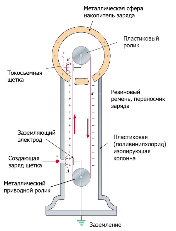 Генератор ван де граафа своими руками. описание и принцип работы
 Освежитель воздуха автоматический air wick: инструкция, сравнение с конкурентами и отзывы
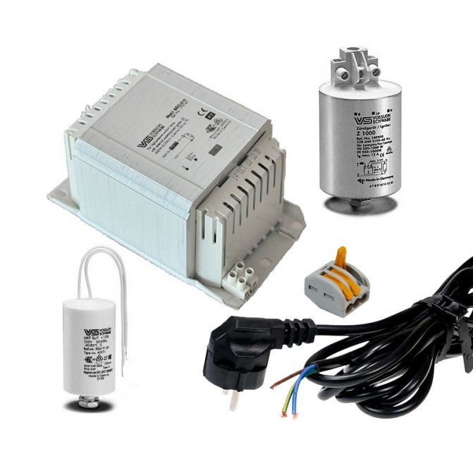 Зачем нужен эпра (электронный балласт) для люминесцентных ламп
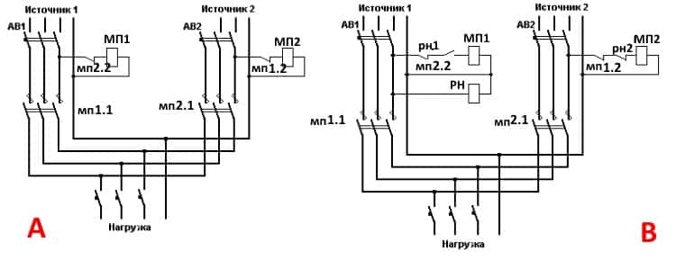 Реверсивный рубильник (переключатель)
 Повтори изобретение легендарного николы теслы! 4 катушки теслы из подручных материалов
 Приливные электростанции